Filling and packaging machine

a technology of packaging machine and filling machine, which is applied in the direction of transportation and packaging, paper/cardboard containers, other domestic objects, etc., can solve the problems of film f meandering, film f is prone to damage, and the sealing condition of the vertically sealed portion can be kept excellent, and the heat sealing is imperfect.

Inactive Publication Date: 2006-02-02
NIPPON SEIKI CO LTD
View PDF6 Cites 113 Cited by
  • Summary
  • Abstract
  • Description
  • Claims
  • Application Information

AI Technical Summary

Benefits of technology

[0012] The present invention relates to a filling and packaging machine adapted to continuously form packaging bags from a film and continuously packaging a material in the bags by carrying out the steps of drawing out and guiding a film from a raw film roll made of a wound film; sending this film to a film folding mechanism adapted to fold back the film in two in the widthwise direction; superposing the two parts of the folded film on each other, vertically sealing the film by a pair of vertically sealing rolls provided in an opposed manner in a vertical sealing mechanism and forming the film cylindrically at this vertically sealed portion; laterally sealing the cylindrically formed film by a pair of laterally sealing rolls provided in a laterally sealing mechanism, and forming a bottom portion of a packaging bag at this laterally sealed portion; filling a material into the film formed to a bottomed cylinder at this bottom portion; and laterally sealing a bag mouth portion of the film as the film is further fed, by the laterally sealing rolls of the laterally sealing mechanism to form a packaged bag and thereby carrying out a continuous packaging operation, wherein the film folding mechanism is provided with an inner surface guide member, which is adapted to guide the film in the widthwise direction thereof, on the side of inner surfaces of the twofold film, left and right preheating block members which are disposed on the side of outer surfaces of the film via clearances of a predetermined width left therebetween so that the preheating block members extend in the widthwise direction of the film, and which have inclined receiving surfaces or arcuate receiving surfaces so that the clearances between the film and preheating block members at an upstream side with respect to the film transfer direction become larger than those between the film and preheating block members at a downstream side with respect to the same direction, and heaters provided in the interior of the preheating block members, the two heater-containing preheating block members provided in the film folding mechanism and having inclined receiving surfaces or arcuate surfaces so that the clearances between the film and preheating block members at an upstream side with respect to the film transfer direction become larger than those between the film and preheating block members at a downstream side with respect to the same direction sending out the twofold film while holding the film tightly between the block members and pressurizing the same at the outer surface thereof in the widthwise direction of the film. Since the parts are arranged in this manner, the contact surface area of the film with respect to the two preheating block members can be increased, so that the film can be preheated as the heat transfer rate of the block members with respect thereto is rendered high. Since the film is sent out as a predetermined contact pressure thereof with respect to the preheating block members is maintained, the film can be heated in advance in a stable condition. Moreover, when the film is vertically sealed in a subsequent step as the film is held between a pair of vertical sealing rolls, the heat is transmitted easily to the thermally fusible resin layer of the film, so that this layer can be melted excellently. Therefore, even when the transfer speed of the film is increased, the sealed condition of the vertically sealed portion can be kept excellent, and the imperfect heat sealing of the portion to be vertically sealed can be prevented. During this time, the film can be preheated by utilizing a part of the film folding mechanism, which is adapted to fold the film in two, also as

Problems solved by technology

This poses a problem of necessarily setting high the preheating temperature of the preheating mechanism 9, and there is also the possibility that a fused layer on the inner side of the film F is melted and damages the film F. This phenomenon would occur noticeably in the structure disclosed in JP-A-2001-72019 in which a preheating mechanism is provided on the inner side of a film to be folded.
When the heated film F is sent into the film folding mechanism, friction is liabl

Method used


Image

  • Filling and packaging machine
  • Filling and packaging machine
  • Filling and packaging machine

Examples


first embodiment

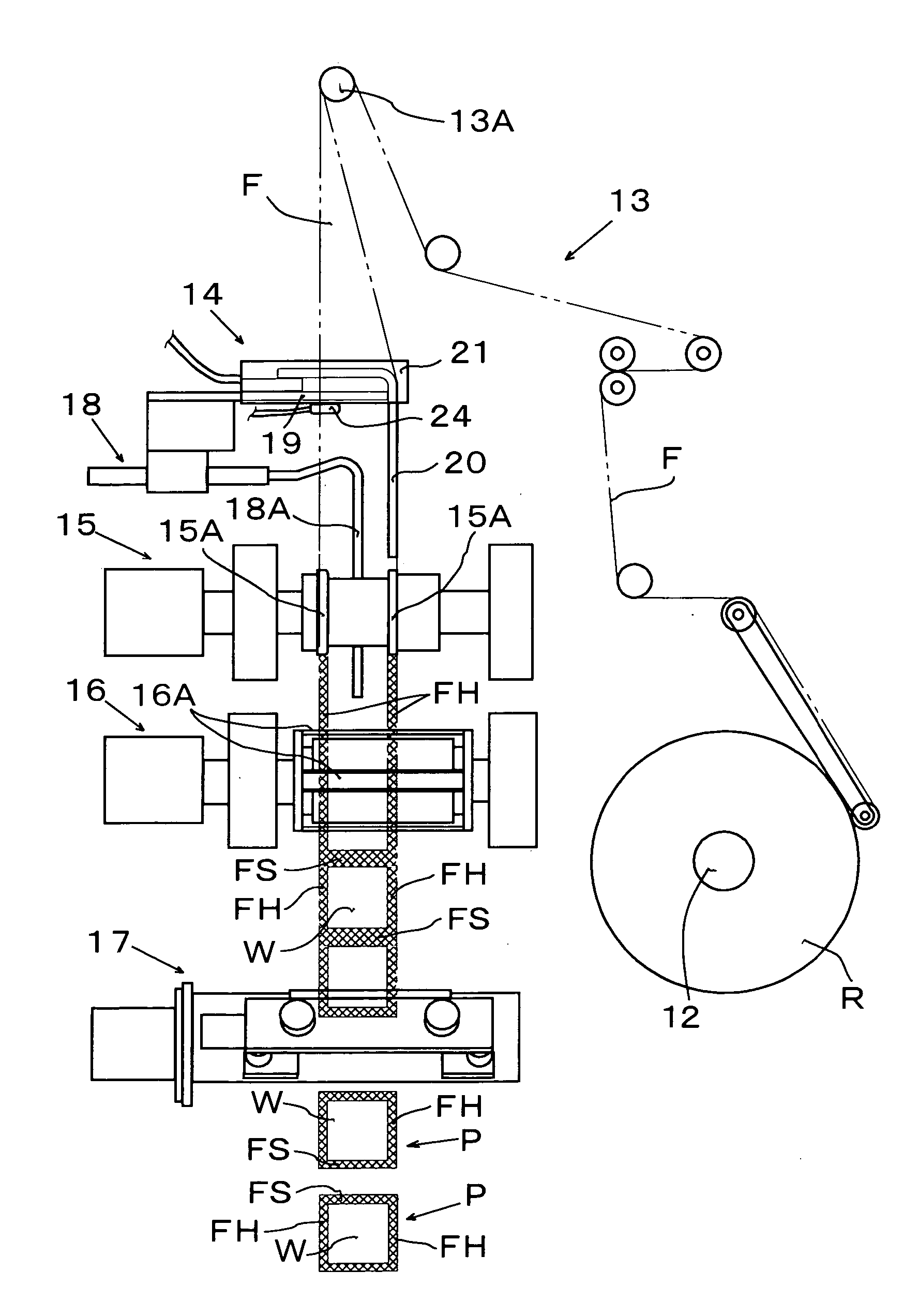
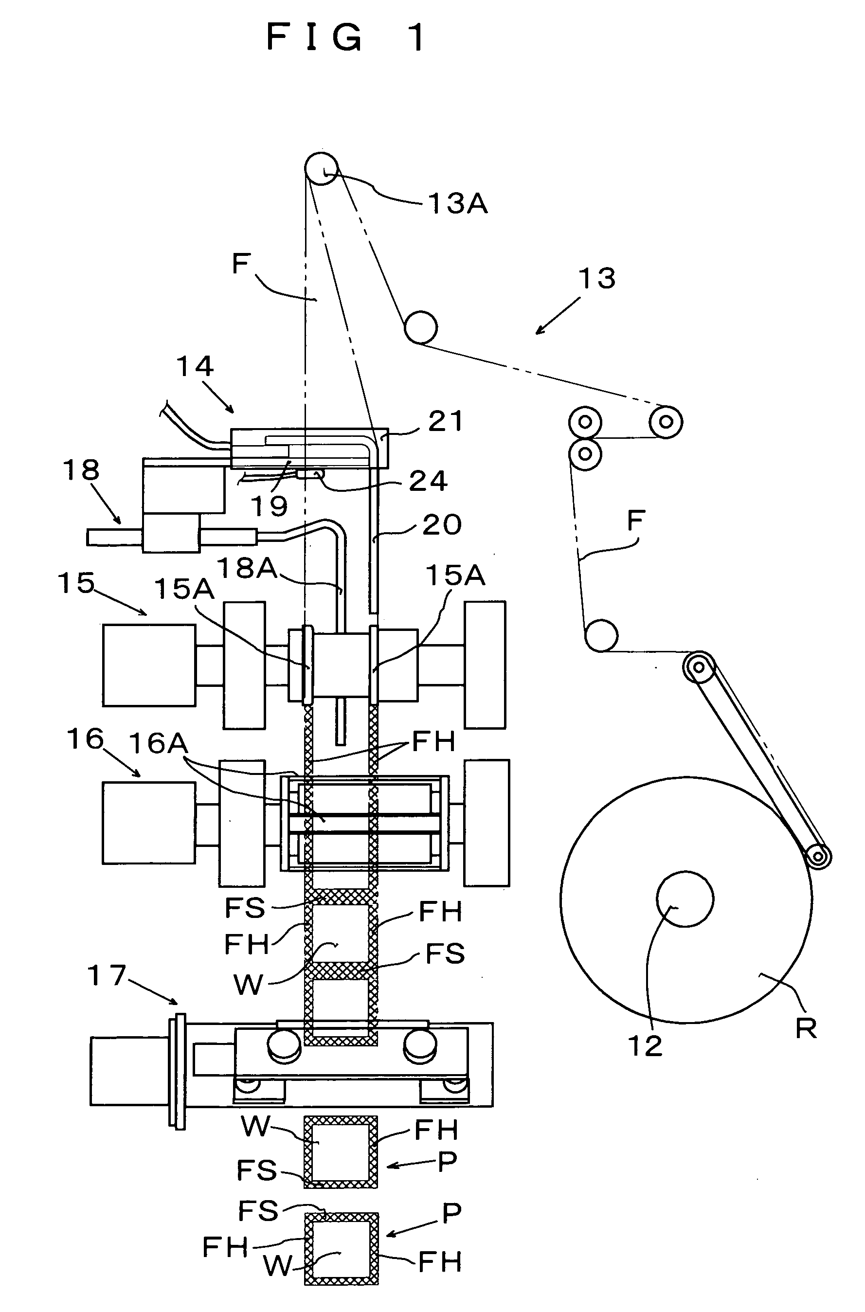
[0027] The present invention will now be described more in detail with reference to the attached drawings. The general schematic construction and operation of the filling and packaging machine according to the present invention will be described with reference to FIG. 1 to FIG. 4.

[0028] Referring to the same drawings showing the general schematic construction of the filling and packaging machine, a raw roll R of film made of a wound film F is mounted and supported on a retainer frame 12 provided on one side of a machine base of the filling and packaging machine. The film F withdrawn and guided from the raw film roll R receives a predetermined level of tension via a film guide mechanism 13 and is withdrawn and guided to a guide roll 13A provided above the machine base of the filling and packaging machine. The film F is then fed from the guide roll 13A to a film folding mechanism 14, which is provided on the lower side of the guide roll 13A, and folded in such a manner that the film F...

second embodiment

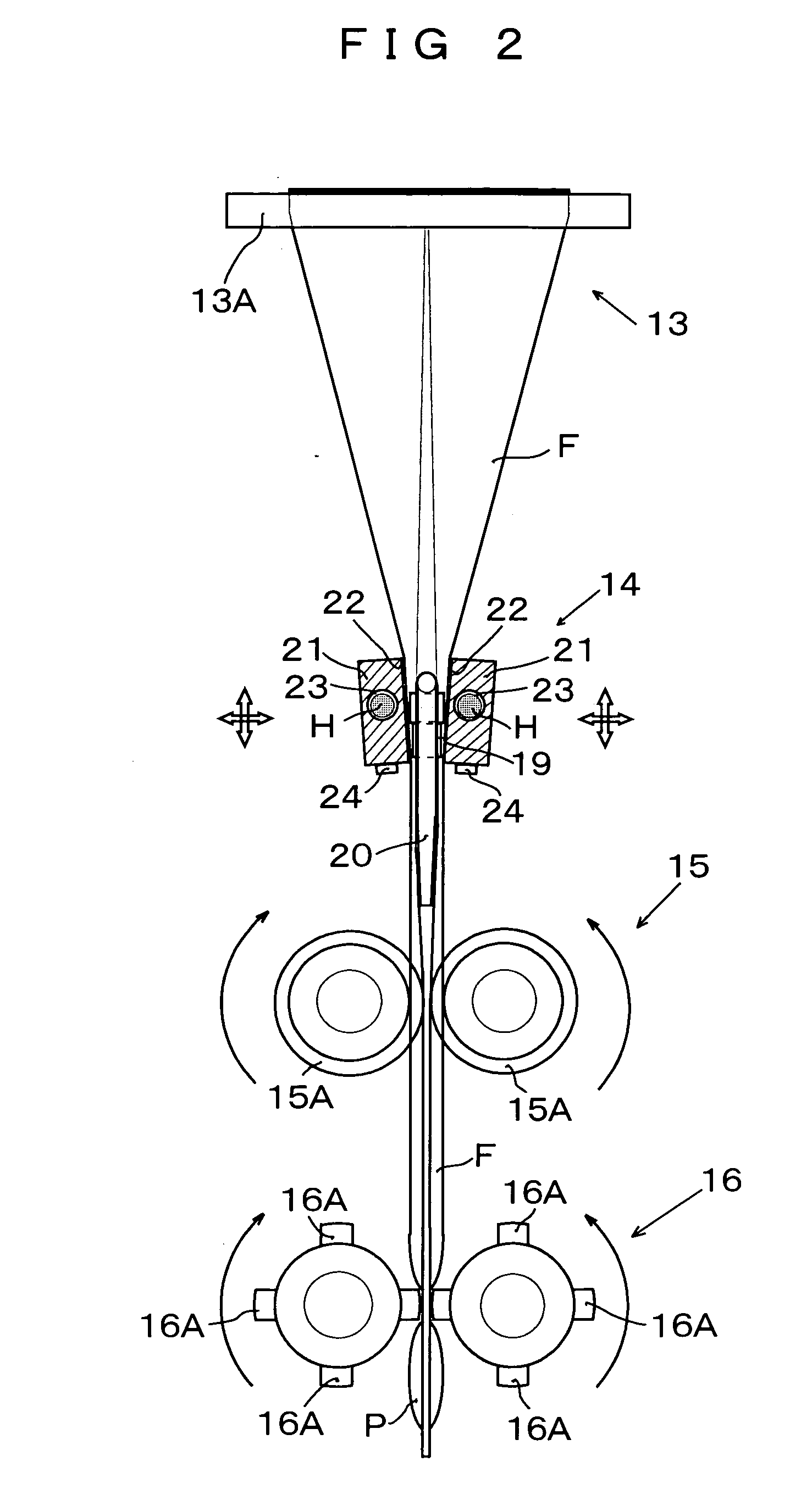
[0042] In this second embodiment, a film folding mechanism 14 is formed by providing at the inner surface side of a twofold film F with an inner surface guide member 19 adapted to guide the film F in the widthwise direction thereof; left and right preheating block members 21 which are provided on the outer surface side of the film F with a predetermined width of space formed between the inner surface guide member 19 and block members 21 so as to extend in the widthwise direction of the film F, and which have arcuate receiving surfaces 33 so that the distance between the receiving surfaces at the upstream side with respect to the transfer direction of the film is larger than that between the receiving surfaces at the downstream side with respect to the same direction; and hollows 23 provided in a portion of each of the preheating block members 21 so that the hollows 23 extend in the lengthwise direction of the block members 21, two heaters H1, H2 being contained in these hollows 23 s...


PUM

PropertyMeasurementUnit
Fractionaaaaaaaaaa
Angleaaaaaaaaaa
Radiusaaaaaaaaaa

Abstract

A filling and packaging machine capable of supplementing the shortage of heat quality without lowering package speed when a film is heat-sealed while being pressurized by a vertical sealing mechanism, comprising a film folding mechanism having an inner surface guide member for guiding the film laterally, formed on the inner surface side of the film folded up into two parts, a pair of right and left pre-heating block members having tilted support surfaces or are support surfaces formed along the width-direction of the film on the outer surface side of the film through a specified interval from the inner surface guide member so that the interval on the upstream side of the film in feeding direction is larger than the interval on the downstream side, and heaters installed in the pre-heating block members.

Description

TECHNICAL FIELD [0001] The present invention relates to a filling and packaging machine adapted to heat seal vertically and laterally three or four sides of a continuously transferred packaging film, and thereby sealing up a material to be packaged, such as a liquid, powder or a viscous material. BACKGROUND ART [0002] A packaging bag into which a material to be packaged, for example, a liquid, powder or a viscous material is filled, the resultant bag being then sealed up has heretofore been formed generally by sealing vertically and laterally three or four sides of a packaging film made of packaging material, such as a film of a synthetic resin or a laminate formed by bonding the same film of a synthetic resin as mentioned above and aluminum foil together. [0003] As an example of a machine for obtaining such a packaging bag, a filling and packaging machine for making three-side-sealed packaging bags will be described by using FIG. 10 and FIG. 11. Referring to the same drawings, a re...

Claims


Application Information

Patent Timeline
IPC IPC(8): B65B9/20B29C65/00B29C65/18B65B9/08B65B51/26
CPCB29C65/18B29C66/91212B29C66/0242B29C66/1122B29C66/232B29C66/3452B29C66/83413B29C66/83513B29C66/849B29C66/91231B29C66/91421B29C66/91423B29L2031/7128B65B9/2021B65B9/207B65B51/306B29C66/024B29C66/81427B29C66/91655B29C65/00B29C65/305B29C66/4312B29C66/4322B29C66/72321B29C66/8432
Inventor TADA, TOSHIOHIRASAWA, TOHRU
Owner NIPPON SEIKI CO LTD
Why Eureka
Try Eureka