Method and system for evaluating fluid flow through a heat exchanger

a heat exchanger and fluid flow technology, applied in the field of heat exchangers, can solve the problems of inability to accurately evaluate the flow of fluid through the heat exchanger, the cooling performance of the evaporator b>32/b> may be compromised, and the internal leakage or bypass of the heat exchanger, etc., to achieve non-destructive evaluation, cost-effective, and rapid

Inactive Publication Date: 2006-02-02
CALSONICKANSEI NORTH AMERICA
View PDF17 Cites 13 Cited by
  • Summary
  • Abstract
  • Description
  • Claims
  • Application Information

AI Technical Summary

Benefits of technology

[0019] Accordingly, it is an advantage of the present invention that a system and method for evaluating a flow of fluid through a heat exchanger are provided.
[0020] It is another advantage of the present invention that a system and method are provided that enable visualization of fluid flow through a heat exchanger.
[0021] Yet another advantage of the present invention is that the system and method enable the rapid, cost effective, and non-destructive evaluation of a heat exchanger for internal leakage.
[0022] The above and other advantages of the present invention are carried out in one form by a method for evaluating a flow of a fluid through a heat exchanger. The method calls for routing the fluid through the heat exchanger, detecting a surface temperature across the heat exchanger in response to a flow of the fluid through the heat exchanger, and determining an efficacy of the flow in response to the surface temperature.
[0023] The above and other advantages of the present invention are carried out in another form by a system

Problems solved by technology

Unfortunately, the cooling performance of evaporator 32 may be compromised when a bypass situation occurs in core 82.
Internal leakage, or bypass, in a heat exchanger can be caused by a faulty manufacturing technique.
Unfortunately,

Method used


Image

  • Method and system for evaluating fluid flow through a heat exchanger
  • Method and system for evaluating fluid flow through a heat exchanger
  • Method and system for evaluating fluid flow through a heat exchanger

Examples


Embodiment Construction

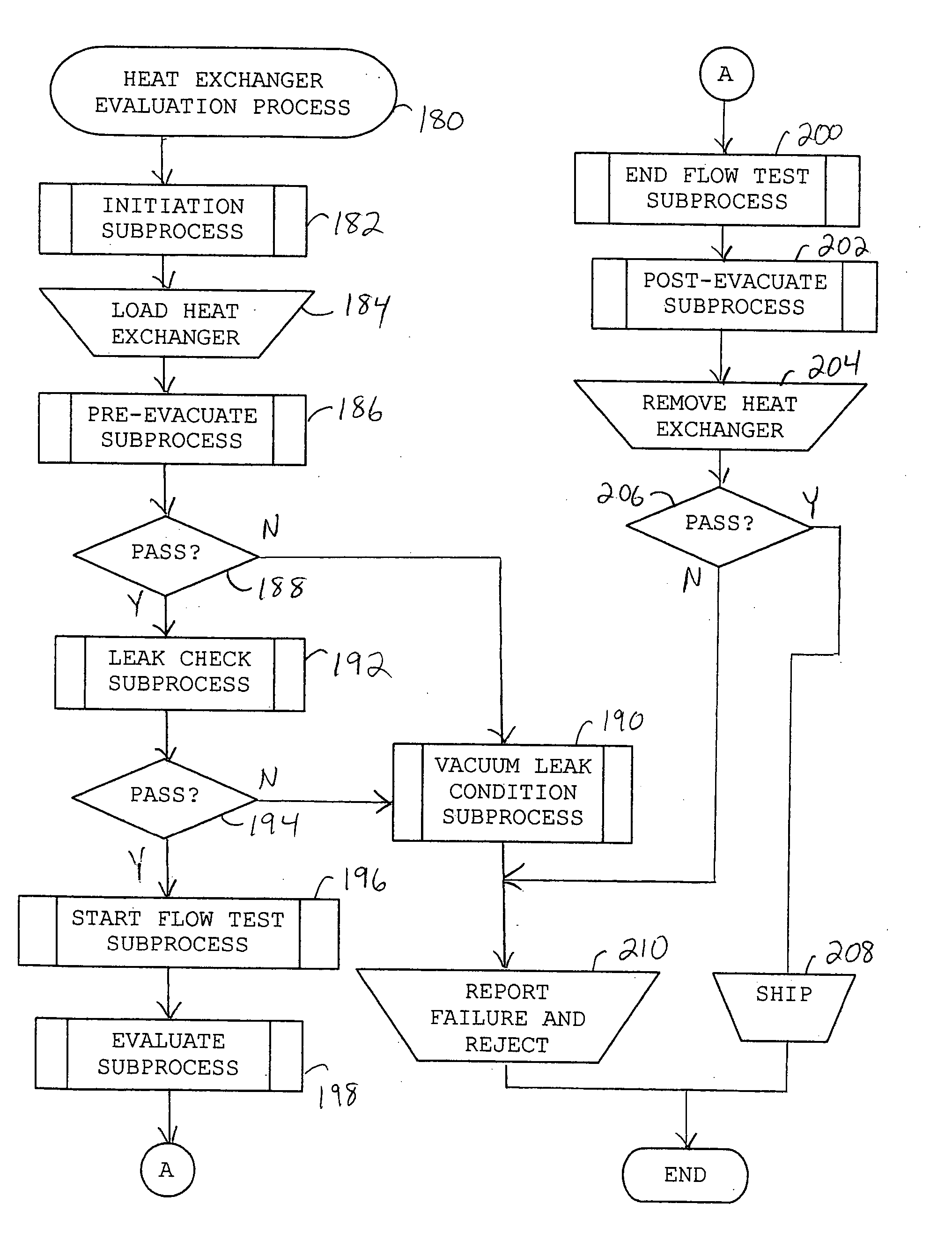
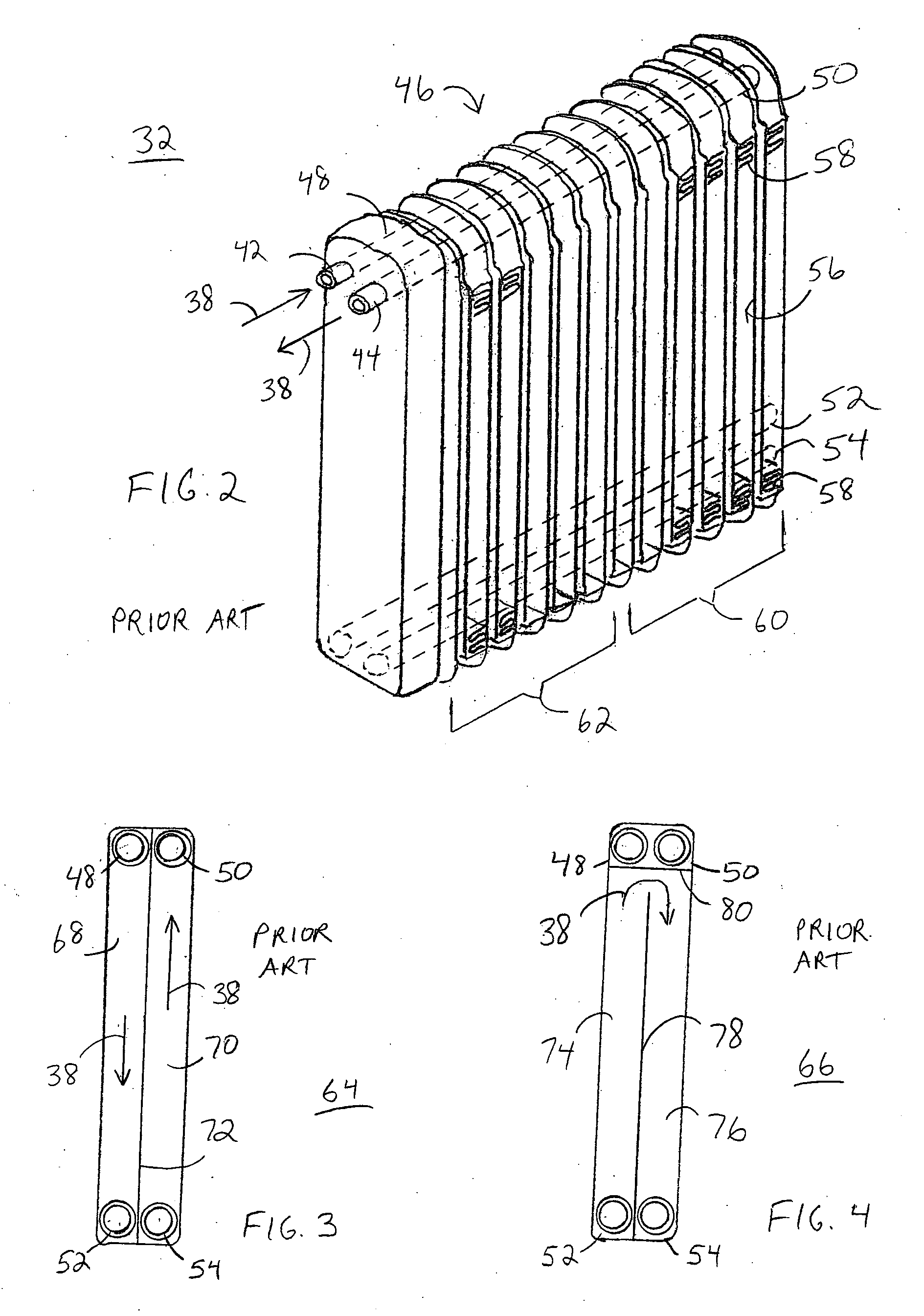
[0043] The present invention involves a system and method for the post-manufacturing evaluation of heat exchangers. Such an evaluation can reveal internal leakage defects in heat exchangers. These defective heat exchangers can then be culled, or rejected, so that they do not enter the market. The present invention will be described in connection with its use for evaluating heat exchanger 32 (FIG. 2). However, it should be readily understood that the present invention may be adapted for testing any of a variety of multiple-pass heat exchangers.

[0044]FIG. 6 shows a block diagram of a component layout of a heat exchanger evaluation system 84 in accordance with a preferred embodiment of the present invention. System 84 includes a mobile test station 86 and a mobile operator station 88. Test station 86 and operator station 88 may be coupled via a bi-directional communication link 90. Mobile test station 86 and mobile operator station 88 are wheeled vehicles, or carts, utilized to convey...


PUM


Abstract

A heat exchanger evaluation system (84) includes a refrigeration subsystem (126) and a platform (94) in communication with the subsystem (126) for attachment of a heat exchanger (32). The system, (84) further includes a thermal imaging camera (168) and a monitor (100). A method (180) entails routing a fluid (38) through the heat exchanger (32) via the refrigeration subsystem (126). The camera (168) detects the temperature variation across the heat exchanger (32) as the fluid (38) flows through the heat exchanger, and provides successive thermal images representing the temperature variation responsive to the flow of the fluid (38). The thermal images are utilized to determine an efficacy of the flow through the heat exchanger (32). In particular, a determination can be made as to whether the flow deviates from a pre-determined flow path (79) of the fluid (38) through the heat exchanger.

Description

TECHNICAL FIELD OF THE INVENTION [0001] The present invention relates to the field of heat exchangers. More specifically, the present invention relates to evaluating a flow of fluid through a heat exchanger. BACKGROUND OF THE INVENTION [0002] A heat exchanger is a device for moving heat from one fluid to another (i.e., from a warm or hot fluid to a cold or cooler one) without allowing the fluids to mix. A heat exchanger typically consists of a series of tubes in which one of the fluids runs. The second fluid runs over the tubes and is heated or cooled. Evaporators, condensers, radiators, and the like are heat exchangers. For example, refrigeration systems, i.e., air conditioners, typically include two heat exchangers, usually referred to as the evaporator and the condenser. [0003]FIG. 1 shows a simplified block diagram of an exemplary refrigeration system 20. Refrigeration system 20 includes a compressor 22 in fluid communication with a condenser 24 via a fluid line 26. Condenser 24...

Claims


Application Information

Patent Timeline
IPC IPC(8): F28D15/00
CPCF28D1/035G01K17/06F28F2200/00G01K2201/00F28F2265/16G01K17/12
Inventor YOUNG, DAVID P.COATES, JOHN ALLENSNOW, JAMES D.
Owner CALSONICKANSEI NORTH AMERICA
Why Eureka
Try Eureka