
Anti-slip device

Active Publication Date: 2006-02-02
MITSUBISHI CABLE IND LTD
View PDF3 Cites 2 Cited by
  • Summary
  • Abstract
  • Description
  • Claims
  • Application Information

AI Technical Summary

Benefits of technology

[0009] It is therefore an object of the present invention to provide an anti-slip device (screw with seat) for carrier tray with which the rubber elastic body is not peeled off by outer force working when the placed liquid crystal panel is attached and detached, and hardly deteriorated when used in etching treatment process.

Problems solved by technology

However, the production process of the conventional jig for carrying is complicated and laborsome because the supporting body, the glue, and the adhesive layer must be layered as not to contain air bubbles.
Further, when the jig for carrying is used for etching treatment process of semiconductors and exposed to corrosive gas in plasmic state, the adhesive layer deteriorates and drops off, and foreign matter sticks to (mixed with) the product.
However, the connection of the supporting plate 1 to the rubber elastic body 2 is not firm, the rubber elastic body 2 may be peeled off when the placed liquid crystal panel is removed.

Method used


Image

  • Anti-slip device
  • Anti-slip device
  • Anti-slip device

Examples


first embodiment

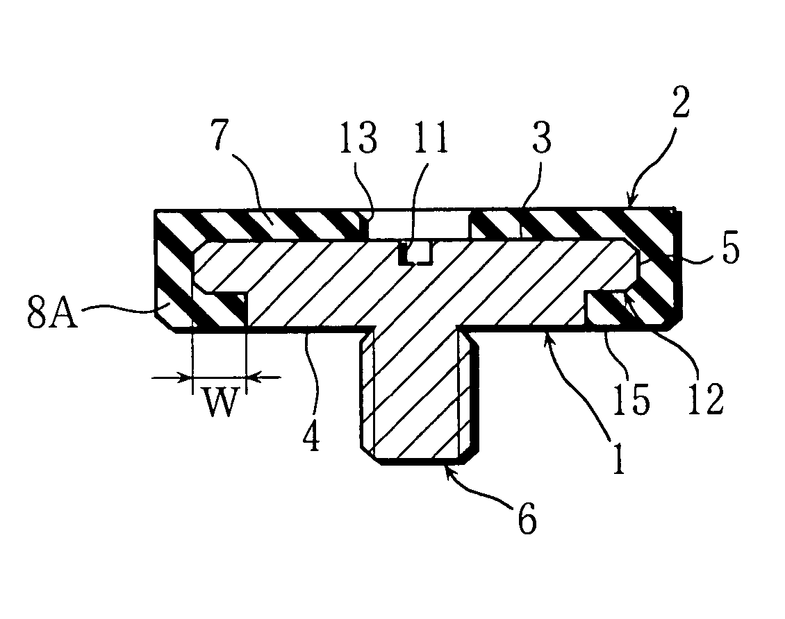
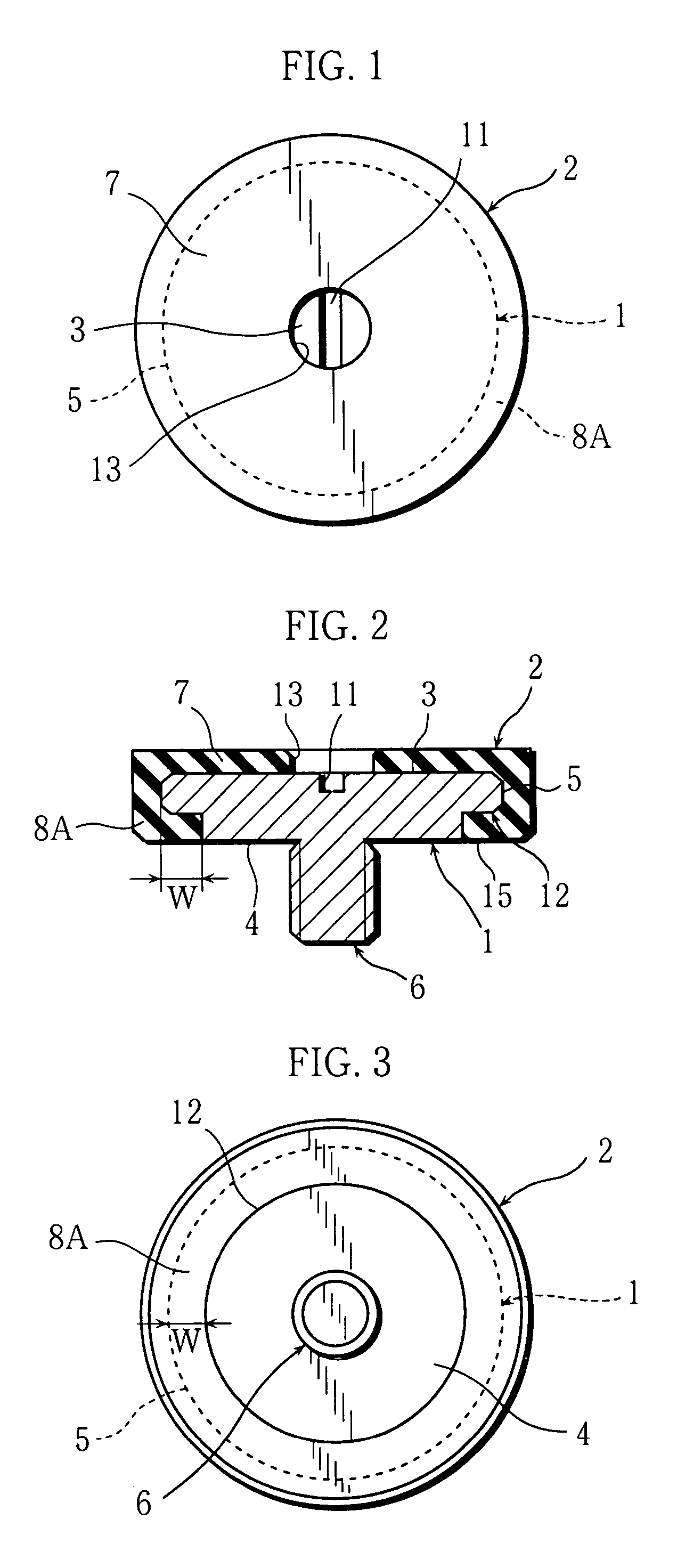
[0028] In a first embodiment shown in FIGS. 1, 2, and 3, a mark 1 represents a supporting plate made of metal or resin, flat and circular in top view. A rubber elastic body 2 is unitedly attached to the supporting plate 1. An attachment portion 6, which can be attached to and detached from another member (such as a carrier tray), is protruding from a center of a reverse face 4 of the supporting plate 1 as to be at right angles with the reverse face 4, and the supporting plate 1 and the attachment portion 6 are unitedly formed. In this case, the attachment portion 6 is formed as a male screw. And, a concave portion 11 for fastening is formed on a center of an obverse face 3 of the supporting plate 1. The concave portion 11 for fastening, formed to be a straight groove as to fit to a minus driver, may be cross, hexagonal, or other configurations. Further, a notched portion 12 of ring, notched with a predetermined width dimension W in a peripheral portion 5, is formed on the reverse fa...

second embodiment

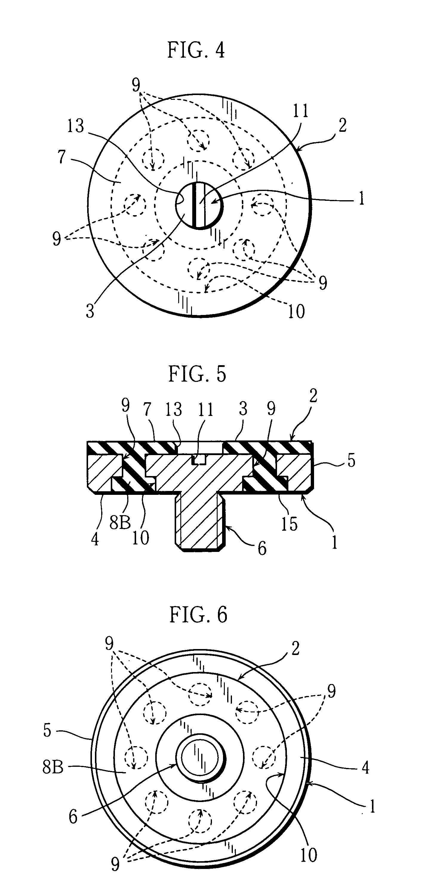
[0033] Next, in a second embodiment shown in FIGS. 4, 5, and 6, the supporting plate 1 and the rubber elastic body 2, unitedly mounted on the supporting plate 1, are provided, a shallow circular concave groove 10 is formed on the reverse face 4 side of the supporting plate 1, and plural connection holes 9, of which lateral cross section is circular, are formed as to go through the obverse face 3 and a bottom wall of the circular concave groove 10.

[0034] The circular concave groove 10 is a square groove as to hold the rubber elastic body 2 onto the supporting plate 1, the plural connection holes 9 are disposed with a predetermined pitch along the peripheral direction, and a diameter dimension of the cross section of the connection hole 9 is set to be smaller than the width dimension of the circular concave groove 10.

[0035] And, inner and outer side walls of the circular concave groove 10 are disposed on the coaxial circle with the peripheral portion 5 of the supporting plate 1 in bo...

third embodiment

[0038] And, in a third embodiment shown in FIGS. 7 through 10, the supporting plate 1 and the rubber elastic body 2, unitedly mounted on the supporting plate 1, are provided, a notched portion 12 of ring, notched with a predetermined width dimension W in a peripheral portion 5, is formed on the reverse face 4 of the supporting plate 1. Further, plural connection holes 9, having circular lateral cross section, are formed from the obverse face 3 to the reverse face 4 of the supporting plate 1, and opening portions of the connection holes 9 on the reverse face 4 side are disposed near the center of the supporting plate 1 within the notched portion 12. As shown in FIG. 9, in a bottom view, the plural connection holes 9 are disposed on a circle coaxial with the center of the supporting plate 1 with a predetermined pitch. And, connecting concave grooves 16 are formed on the reverse face 4 of the supporting plate 1 to connect the connection holes 9 and the notched portion 12, and the conne...


PUM


Abstract

An anti-slip device provided with a supporting plate of metal or resin having an attachment portion on a reverse face for other members, and a rubber elastic body unitedly mounted on the supporting plate. Plural connection holes are formed from an obverse face to the reverse face of the supporting plate. Further, the rubber elastic body is composed of a receiving piece portion covering approximately whole of the obverse face and a falling-prevention portion from the reverse face to connect the receiving piece portion through a peripheral portion and the connection hole.

Description

BACKGROUND OF THE INVENTION [0001] 1. Field of the Invention [0002] This invention relates to an anti-slip device for carrier tray for semiconductors, liquid crystal panels, and large glass plates used in carrying device for liquid crystal panels and large glass plates of plasma TV. [0003] 2. Description of the Related Art [0004] In a production line of liquid crystal panels, the liquid crystal panels are placed on carrier trays or fixed to frames like architraves to be moved on a conveyer. When the carrier tray in a carrying state stops, the liquid crystal panel slips on the tray and deviates from a right position, and deformation is generated on a central portion by sagging for self weight of the panel when the panel is large-sized. These are supposed not to occur in the production process of the liquid crystal panels in which surface treatment is conducted with high dimensional accuracy. [0005] To solve the problem above, conventionally, a jig is made by serially layering glue an...

Claims


Application Information

Patent Timeline
IPC IPC(8): B65G47/00
CPCF16M13/00F16M11/22F16M2200/08G02F1/13
Inventor NISHIDA, KAZUMASA
Owner MITSUBISHI CABLE IND LTD
Features
  • Generate Ideas
  • Intellectual Property
  • Life Sciences
  • Materials
  • Tech Scout
  • Unparalleled Data Quality
  • Higher Quality Content
  • 60% Fewer Hallucinations
Learn More