Scanner with color profile matching mechanism

a color profile matching and scanner technology, applied in the field of scanners with color profile matching mechanisms, can solve the problems of image that does not accurately recreate the colors of the scanned image, degrades or deteriorates, and deterioration of light sources

Inactive Publication Date: 2006-02-02
AVAGO TECH ECBU IP (SINGAPORE) PTE LTD
View PDF20 Cites 53 Cited by
  • Summary
  • Abstract
  • Description
  • Claims
  • Application Information

AI Technical Summary

Problems solved by technology

One problem encountered for the above scanner systems is the deterioration or degradation of the light source.
Unfortunately, upon the passage of time, the performance of the LED (e.g., red LED) degrades or deteriorates so that the LED generates less red light than the LED originally generated.
However, after the passage of time, the red LED may provide only 15 k LUX of red light instead of 20 k LUX when supplied with the same 1 mA of current.
As can be appreciated, when the light generated by the light source is not a pure white light, the scanner produces output images that do not accurately re-create the colors of the scanned image.
Furthermore, degradation of the light source adversely affects scan quality of the scanner.
Consequently, the scanned version may not accurately reproduce the actual colors of the scanned image.

Method used


Image

  • Scanner with color profile matching mechanism
  • Scanner with color profile matching mechanism
  • Scanner with color profile matching mechanism

Examples


Embodiment Construction

[0015] Scanner with color profile matching mechanism is described. In the following description, for the purposes of explanation, numerous specific details are set forth in order to provide a thorough understanding of the present invention. It will be apparent, however, to one skilled in the art that the present invention may be practiced without these specific details. In other instances, well-known structures and devices are shown in block diagram form in order to avoid unnecessarily obscuring the present invention.

[0016] Scanner 100

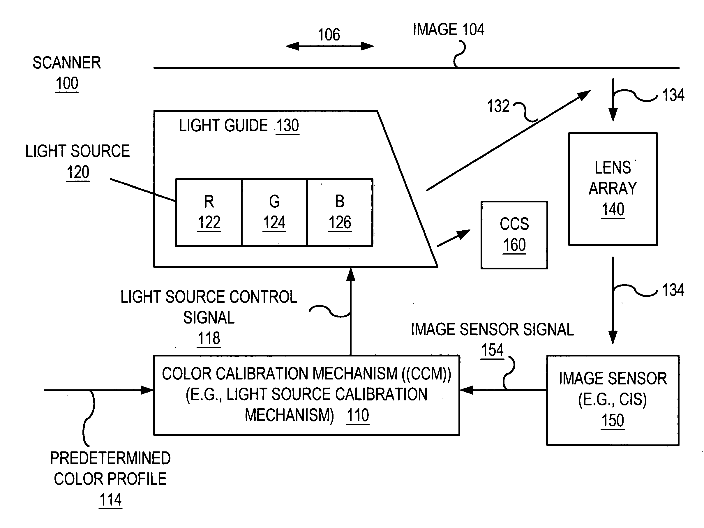
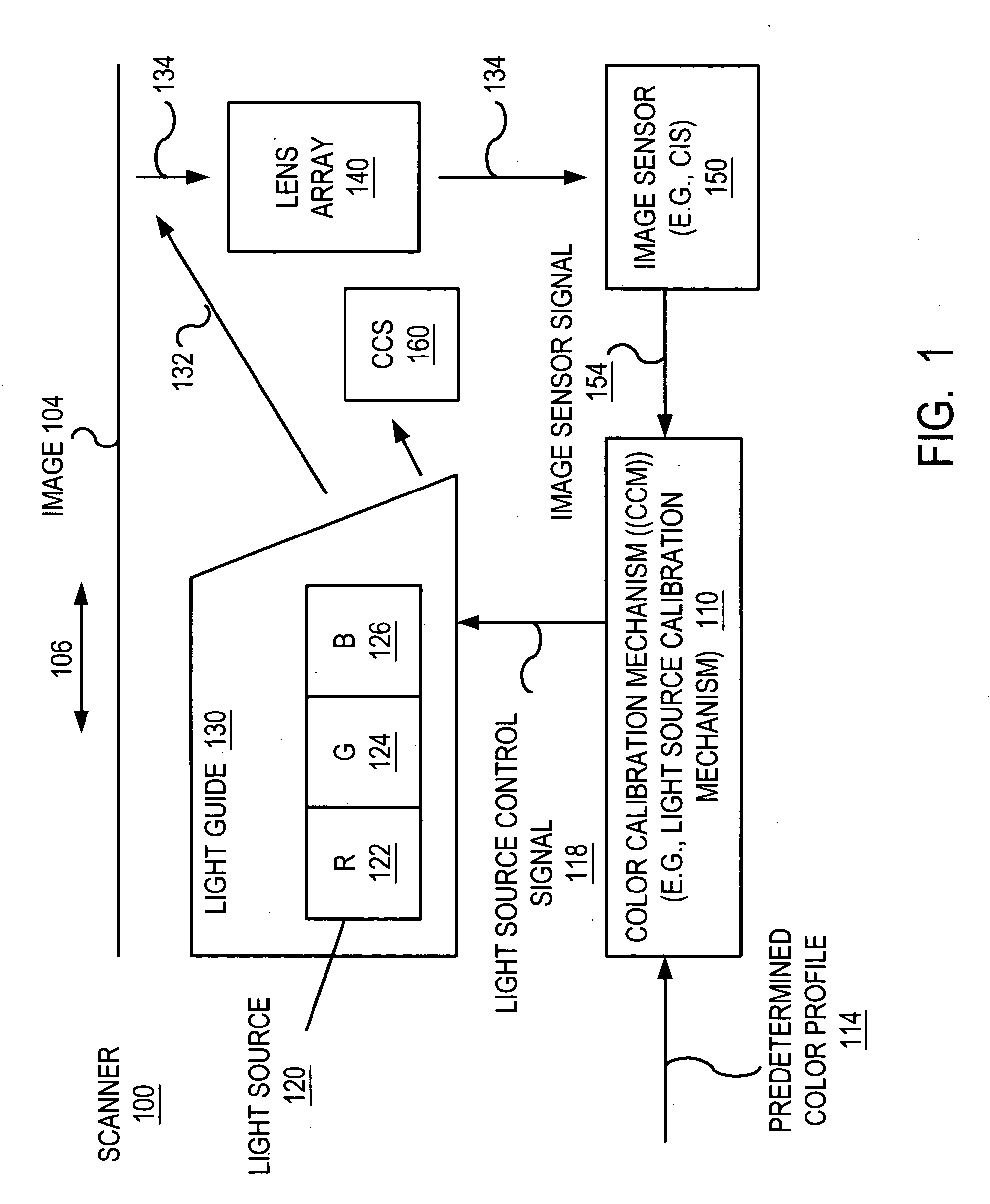
[0017]FIG. 1 illustrates a scanner 100 that utilizes a color calibration mechanism (CCM) 110 according to one embodiment of the invention. The scanner 110 scans images (e.g., image 104). The scanner 100 is configured to sense an image 104 that is disposed on the bottom surface of a document, for example. The image 104 is moved longitudinally in one of the directions shown by the double-sided arrow 106 so that a single scan line across the width of the...


PUM


Abstract

Scanner with light source calibration mechanism. The scanner includes a light source that generates a white light utilized to scan an image. The light source calibration mechanism includes a calibration color sensor that generates a calibration color sensor output. The light source calibration mechanism receives a predetermined color profile that can be, for example, the amount of red, green light, and blue light expected from the light source utilized by the scanner for scanning. The color calibration mechanism calibrates the light source of the scanner based on the output of the calibration color sensor and the predetermined color profile.

Description

BACKGROUND OF THE INVENTION [0001] Image scanning devices such as, for example, flat bed image scanners and sheet feed image scanners, are commonly used to scan documents containing image information to convert the image information contained on the document into a digital representation of the document. Image scanning devices typically utilize a linear imaging device, which is scanned across a document being imaged to produce multiple one-dimensional (1-D) slices of the image, which are subsequently processed and combined to produce a two-dimensional (2-D) digital representation of the image contained on the document. [0002] The image scanning device utilizes a light source to project light onto the document being scanned. The light reflected from the document is focused by imaging optics onto the linear imaging device. The linear imaging device includes one or more photo sensors that convert the light reflected from the document into analog signals. The analog signals are then con...

Claims


Application Information

Patent Timeline
Patent Type & Authority Applications(United States)
IPC IPC(8): H04N1/46
CPCH04N1/40056H04N1/4005
Inventor BOAY, YOKE PENGKEH, KEAN LOOOON, CHIN HINMANIAM, SELVANWONG, KING WAI
Owner AVAGO TECH ECBU IP (SINGAPORE) PTE LTD
Why Eureka
Try Eureka