Light source device including a planar light source having a single, substantially continuous light emission area and display device incorporating the light source device

a light source device and substantially continuous technology, applied in the direction of static indicating devices, instruments, optics, etc., can solve the problems of deteriorating display image resolution, high cost, and difficulty in further miniaturization of display devices

Inactive Publication Date: 2005-04-19
SEIKO EPSON CORP
View PDF49 Cites 91 Cited by
  • Summary
  • Abstract
  • Description
  • Claims
  • Application Information

AI Technical Summary

Benefits of technology

[0007]With the foregoing in view it is an object of the present invention to use only one liquid crystal display element, in order to miniaturize the display device, and to miniaturize the overall display device by making the light source device compact.
[0008]It is a further object to provide, even in a display device using a single liquid crystal display element, a display device wherein the light from the light source device is used with high efficiency, and which is capable of displaying images of high resolution.

Problems solved by technology

With the first prior art, cited above, however, because three liquid crystal display elements are used, costs becomes high, which is a problem, and an adjustment mechanism become necessary for keeping the images of the three liquid crystal display elements from shifting out of place, which makes it very difficult to realize further miniaturization in the display devices, which is also a problem.
Three pixels, namely a red, a green, and a blue pixel are necessary in order to generate colors, whereupon display image resolution deteriorates, and, since light other than that of the transmission wavelength is absorbed by the color filters, the display images become dark, which is a problem.
In addition, a high voltage is required for lighting the metal halide lamp, which means that the power supply circuit becomes large, thus making it very difficult to miniaturize the display device, which is a problem.

Method used


Image

  • Light source device including a planar light source having a single, substantially continuous light emission area and display device incorporating the light source device
  • Light source device including a planar light source having a single, substantially continuous light emission area and display device incorporating the light source device
  • Light source device including a planar light source having a single, substantially continuous light emission area and display device incorporating the light source device

Examples


first embodiment

[0082](First Embodiment of Light Source Device)

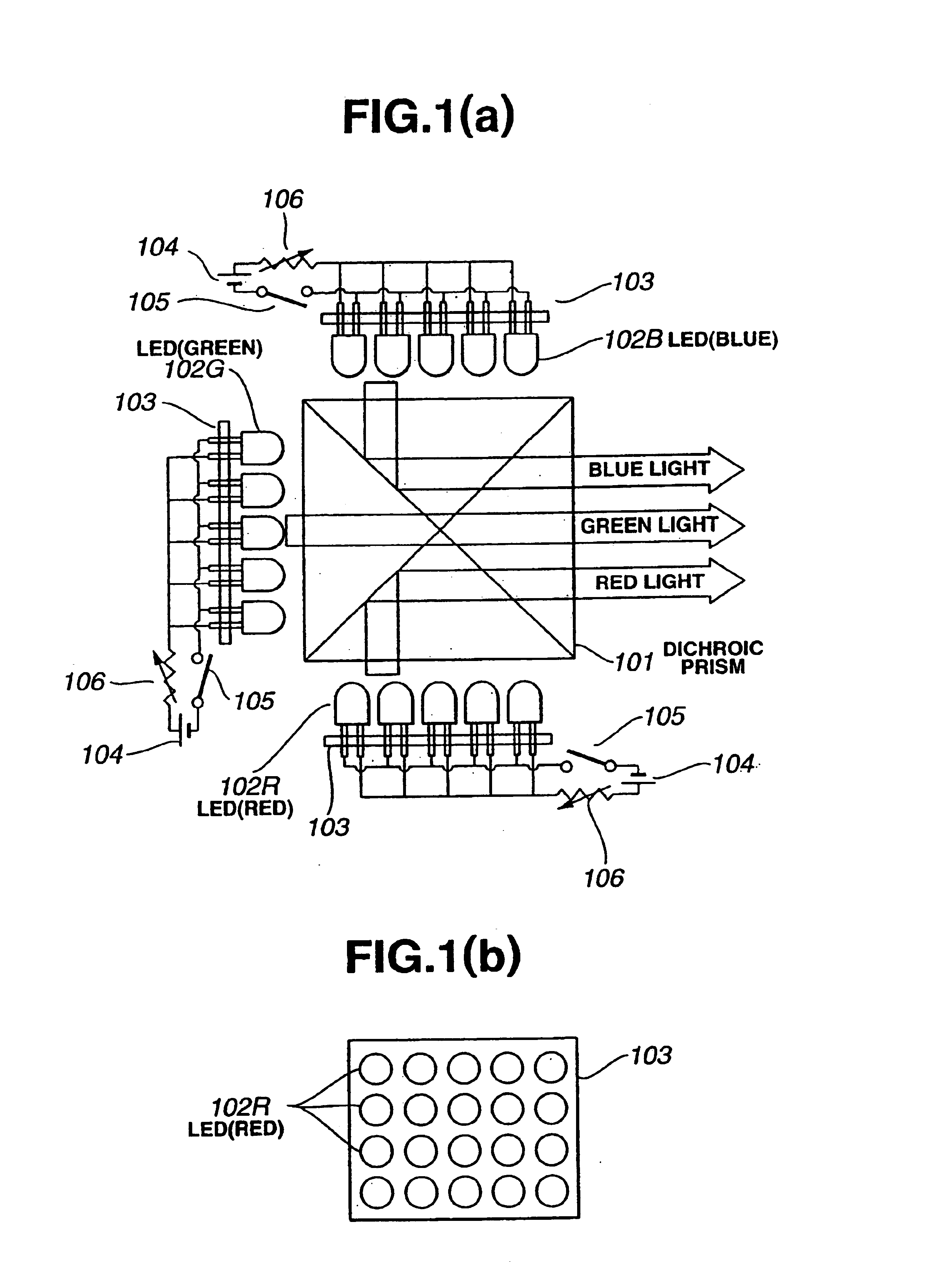
[0083]A first embodiment of the light source device of the present invention is described on the basis of FIG. 1. FIG. 1(a) is a diagram of the light source device as seen from above; FIG. 1(b) is a plan of a red light source as seen from the side of a dichroic prism serving as a color synthesizing optical system.

[0084]About the periphery of a dichroic prism 101 are deployed a red light source, a green light source, and a blue light source that are configured from two-dimensional arrays of light emitting diodes (LEDs).

[0085]The red light source is a structure wherein LEDs 102R (red) that emit light of a wavelength in the red region are fixed to a board 103. Electric power is supplied to the LEDs 102R (red) from a DC power supply 104 via a switch 105 and a variable resistor 106.

[0086]LEDs having a peak light emission wavelength of 620 nm can be used for the LEDs 102R (red). In that case, the color of the emitted light will appear to be o...

second embodiment

[0095](Second Embodiment of Light Source Device)

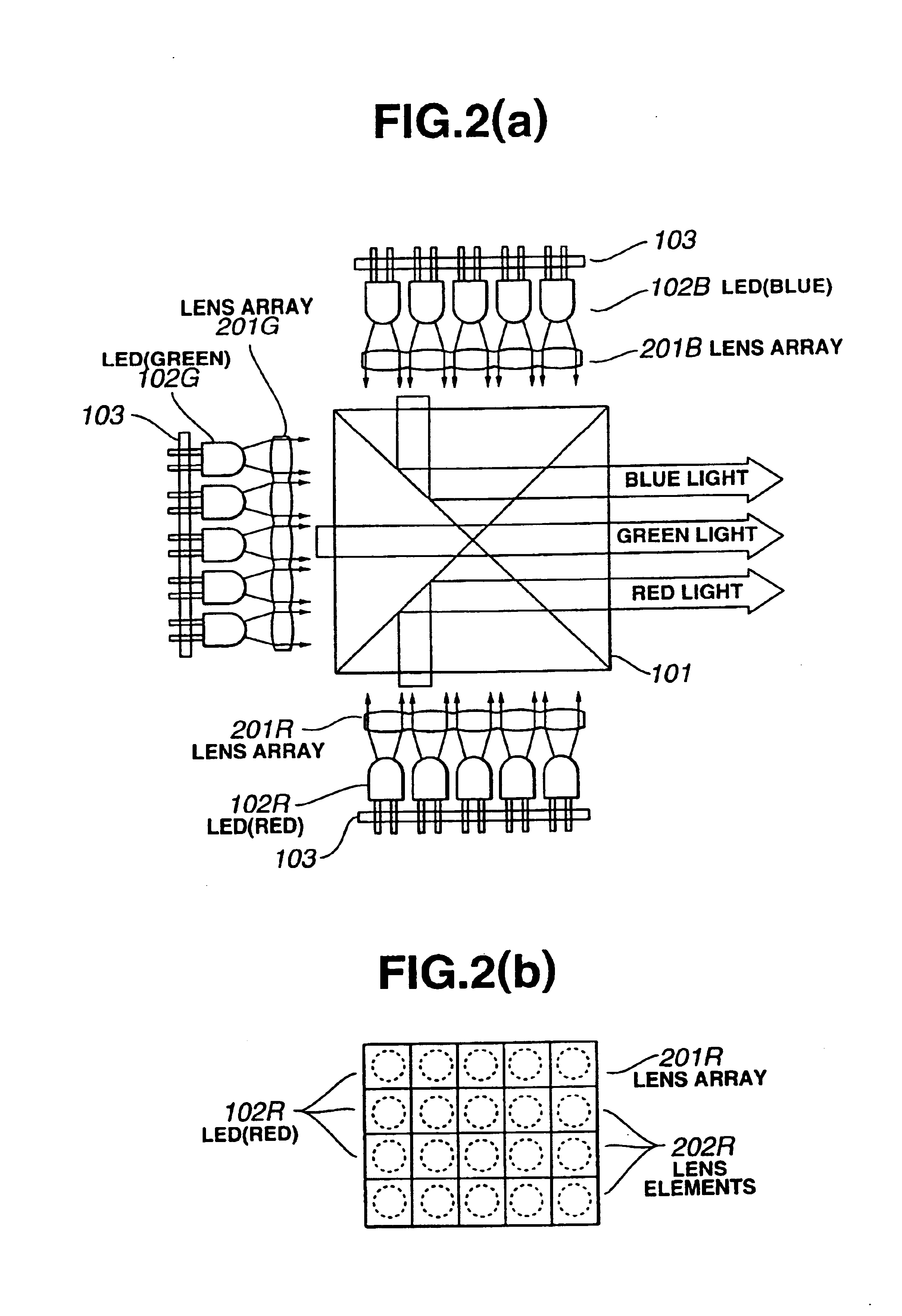
[0096]A second embodiment of the light source device of the present invention is described on the basis of FIG. 2. FIG. 2(a) is a diagram of the light source device as seen from above; FIG. 2(b) is a plan of a red light source as seen from the dichroic prism side.

[0097]In FIG. 2(b), the LEDs 102R (red) corresponding to lens elements 202R configuring a lens array 201R are described by dotted lines. In FIG. 2(a), moreover, the electrical circuitry for the light source, such as is diagrammed in FIG. 1(a), is not shown.

[0098]About the periphery of the dichroic prism 101 are deployed a red light source, green light source, and blue light source that are configured of two-dimensional arrays of light emitting diodes (LEDs).

[0099]The red light source is configured of an array of LEDs 102R (red) that emit light of a wavelength in the red region, and a lens array 201R deployed between these LEDs and the dichroic prism. The lens array 201R is con...

third embodiment

[0107](Third Embodiment of Light Source Device)

[0108]A third embodiment of the light source device of the present invention is described on the basis of FIG. 3. FIG. 3 is a diagram of the light source device as seen from above.

[0109]About the periphery of a dichroic prism 101 are deployed a flat-panel fluorescent tube 301R (red) emitting light of a wavelength in the red region, a flat-panel fluorescent tube 301G (green) emitting light of a wavelength in the green region, and a flat-panel fluorescent tube 301B (blue) emitting light of a wavelength in the blue region.

[0110]These fluorescent tubes 301R, 301G, and 301B of the various colors comprise light emitting bodies that, respectively, are a fluorescent body that emits light which is red, a fluorescent body that emits light which is green, and a fluorescent body that emits light which is blue. Each of these fluorescent tubes has a planar size such that the light emission area is on the order of 19 mm×14 mm. The size of the fluoresc...


PUM

PropertyMeasurementUnit
voltageaaaaaaaaaa
peak light emission wavelengthaaaaaaaaaa
diametersaaaaaaaaaa

Abstract

A red light source comprising an array of LEDs 102R that emit light of a red color, a green light source comprising an array of LEDs 102G that emit light of a green color, and a blue light source comprising an array of LEDs 102B that emit light of a blue color are deployed about the periphery of a dichroic prism 101. A liquid crystal display element is illuminated by a light source device configured such that the light from the respective light sources is synthesized into white light by the dichroic prism, and projection type liquid crystal display devices and the like are configured.

Description

TECHNICAL FIELD[0001]The present invention relates to the configuration of a light source device in a display device for the magnification and projection of images displayed in liquid crystal display elements, and to the configuration of a display device using that light source device.BACKGROUND ART[0002]The technology disclosed in Japanese Patent Application Laid-Open No. H5-13049 / 1993, as published, may be cited as first prior art for miniaturizing projection type liquid crystal display devices which magnify, project, and display images of liquid crystal display elements.[0003]Disclosed in this publication is the configuration of a display device wherein three liquid crystal display elements are deployed about the periphery of a dichroic prism, the liquid crystal display elements are illuminated by flat-panel fluorescent tubes emitting different colors of light, respectively, deployed on the back sides of the liquid crystal display elements, and images of the several colors synthe...

Claims


Application Information

Patent Timeline
Patent Type & Authority Patents(United States)
IPC IPC(8): G02F1/1335G02F1/13G02B27/14G02F1/13357
CPCG02B27/1033G02B27/1053G02B27/1066G02B27/144G02B27/149G02F1/133609G09G2310/0235G02F2001/133607G02F2001/133622G09G3/3406G09G3/3413G02F1/133622G02F1/133607
Inventor YOKOYAMA, OSAMUSHIMODA, TATSUYAMIYASHITA, SATORU
Owner SEIKO EPSON CORP
Why Eureka
Try Eureka