Light emitting device having function of heat-dissipation and manufacturing process for such device

a technology of light-emitting devices and manufacturing processes, which is applied in the direction of semiconductor devices for light sources, light-emitting devices, point-like light sources, etc., can solve the problems of low heat-dissipation efficiency, low illuminating efficiency and short life time, and low heat-dissipation efficiency, so as to prevent heat accumulation in printed circuit boards, high thermal conductivity, and high stability

Inactive Publication Date: 2009-06-04
ADVANCED CONNECTEK INC +1
View PDF3 Cites 91 Cited by
  • Summary
  • Abstract
  • Description
  • Claims
  • Application Information

AI Technical Summary

Benefits of technology

[0009]The main object of the present invention is to provide a composite structure and packaging method of a heat-dissipation module, wherein light-emitting diodes (especially LED chip die) are directly packaged on a post-like metal material in the form of “chip on heat-dissipation board”, to achieve high thermal conductivity and high stability to prevent heat accumulation in a printed circuit board and thus prolong the life time of light-emitting diodes.

Problems solved by technology

However, the present LED light bulbs are usually fabricated by multiple-level-package with several packaging interfaces, which may cause thermal resistance, especially heat may accumulate on the printed circuit board and lead to a low heat-dissipation efficiency.
Due to the insufficient heat-dissipation capability, the temperature of LED can not be effectively reduced, which results in low illuminating efficiency and short life time.
In addition, when the number of LED is increased for a higher illumination, the number of source electrodes is accordingly increased, which results in the aforementioned problem of lower heat-dissipation and gets troubles in arranging the electrodes and occupying more available area.
However, the heat-dissipation base material may contact with other conductors and make the circuitry short to damage the LED and reduce the yield factor.
Furthermore, although the LED is gradually applied in illumination, it is not compatible with the present lamps yet.
The problem of incompatibility not only limits the illuminating application of LED, but also requires a lot of cost to replace the incompatible lamps for LED, which is neither economical nor environmentally friendly.

Method used


Image

  • Light emitting device having function of heat-dissipation and manufacturing process for such device
  • Light emitting device having function of heat-dissipation and manufacturing process for such device
  • Light emitting device having function of heat-dissipation and manufacturing process for such device

Examples


first embodiment

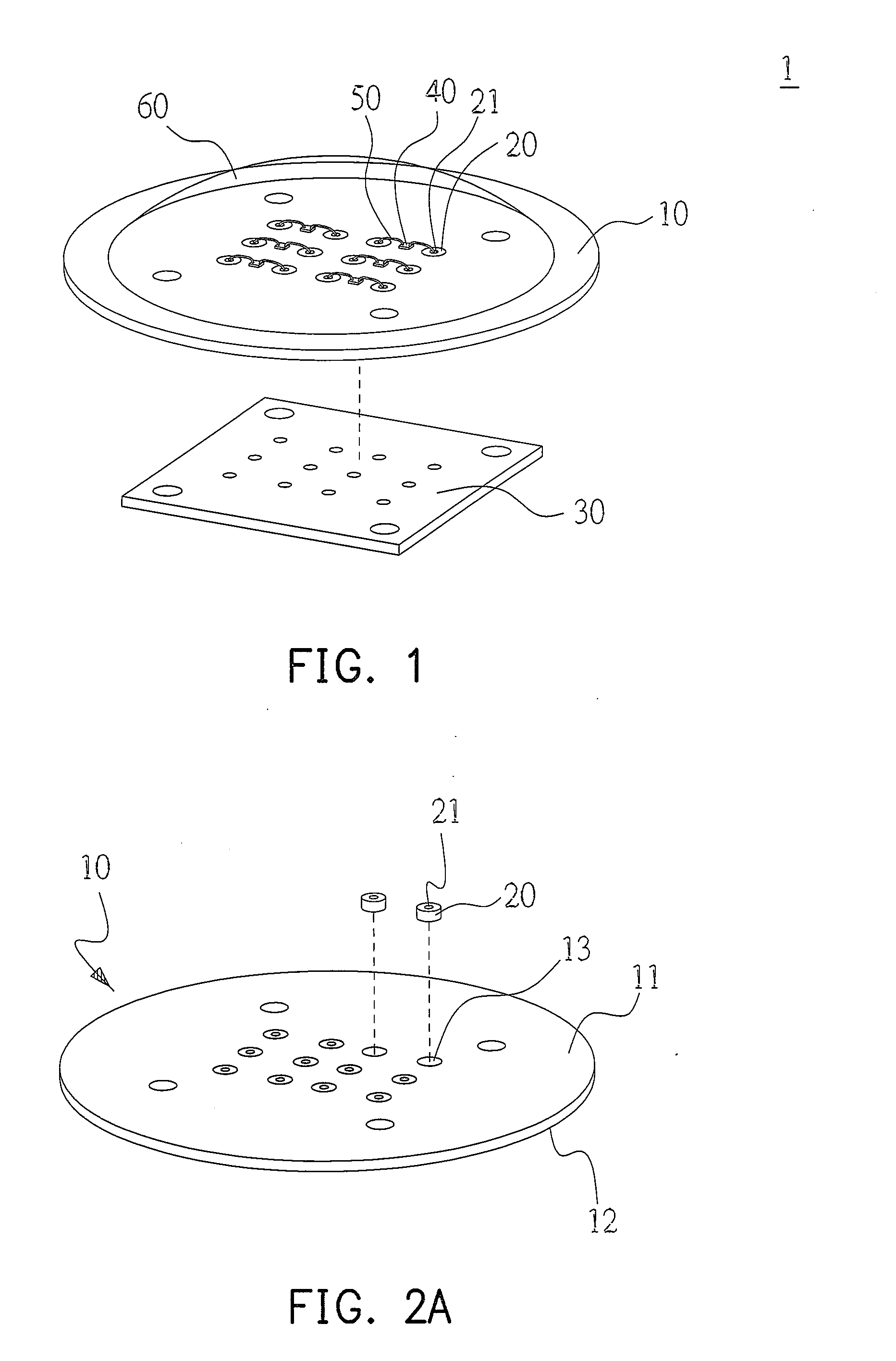
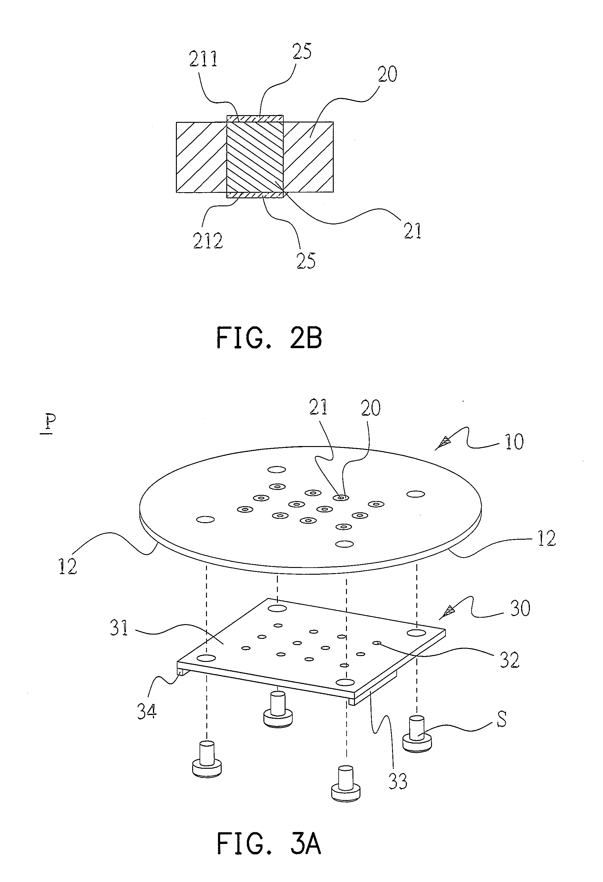
[0033]FIG. 1 is a schematic structure diagram of the light-emitting device 1 of the present invention. The main structure of this light-emitting device 1 includes a post-like metal material 10, conductors 21, insulators 20 encapsulating the conductors 21, a printed circuit board 30, light-emitting diodes 40, wires 50, and an encapsulating material 60.

[0034]Please refer to FIGS. 2A and 2B. The post-like metal material 10 is metallic and post-like. For example, the post-like metal material 10 can be a cylinder or polygonal column. The first embodiment takes the cylindrical profile as an example. The post-like metal material 10 can be made of pure copper, copper alloy, pure aluminum, aluminum alloy, or a composite material of copper and aluminum. The post-like metal material 10 includes a first surface 11, a second surface 12, and a plurality of through holes 13 passing through the first surface 11 and the second surface 12. The conductors 21 are used to transmit electricity and are po...

second embodiment

[0038]Referring to FIG. 5A illustrating the present invention, other than the above mentioned manner of disposing the light-emitting diodes 40 and the wires 50, the light-emitting diodes 40 and the wires 50 can further be packaged into a light-emitting unit 8 first, and then be directly soldered or adhered on to the first surface 11 of the post-like metal material 10 of the composite heat-dissipation substrate P. Please refer to FIG. 5B. Each light-emitting unit 8 includes a substrate 81, a heat-dissipation base 82, at least one light-emitting diode 40, a plurality of wires 50, two electrode terminals 83, 84, and encapsulating material 60. The substrate 81 is an insulator, including a first surface 811, a through hole 812, and an electrical circuit 813 disposed on the first surface 811. The heat-dissipation base 82 is post-like and disposed in the through hole 812 of the substrate 81, wherein the heat-dissipation base 82 includes a top surface 821 and a bottom surface 822. The light...


PUM

PropertyMeasurementUnit
conductiveaaaaaaaaaa
temperatureaaaaaaaaaa
thicknessaaaaaaaaaa

Abstract

A light-emitting device of a light-emitting diode (LED) and a manufacture method thereof are provided. The light-emitting device includes a post-like metal material, a printed circuit board, conductors, insulators, light-emitting diodes, wires, and an encapsulating material. The light-emitting device has through holes, in which conductors are disposed and surrounded with the insulators. One end of each conductor is connected to the printed circuit board to form a composite structure heat-dissipation substrate. The light-emitting diodes are disposed on the post-like metal material, connected to the conductors via the wires, and encapsulated by the encapsulating material. Furthermore, the light-emitting diodes, the wires, and the encapsulating material can be combined into a light-emitting unit. Moreover, red, blue, and green light-emitting diodes can be combined and the color of output light thereof can be adjusted by controlling the input signal.

Description

CROSS-REFERENCE TO RELATED APPLICATION[0001]This application claims the priority benefit of Taiwan application serial no. 96145693, filed on Nov. 30, 2007. The entirety of the above-mentioned patent application is hereby incorporated by reference herein and made a part of specification.BACKGROUND OF THE INVENTION[0002]1. Field of Invention[0003]The present invention relates to a light-emitting device and manufacture method thereof. The light-emitting device integrates the functions of an electronic substrate and a heat-dissipation module to manage the thermal conducting and electrical conducting individually. Volume of the light-emitting device can be reduced and accordingly the application field of the same is wide. The light-emitting device can be further incorporated with the existing lamp holder to form a light bulb for illumination.[0004]2. Description of Related Art[0005]Light-emitting diode (LED) is characterized by long life time, high illumination, high illuminating efficie...

Claims


Application Information

Patent Timeline
Patent Type & Authority Applications(United States)
IPC IPC(8): H01L33/00H01L21/00H01L33/64
CPCF21K9/137F21V29/767F21Y2101/02H01L33/642H05K3/32H05K3/4015H05K2201/10106H05K2201/10242H05K2201/10378H05K2201/10424H05K2201/10962H01L2224/48091H01L2224/48247F21V7/22F21V29/745F21V29/505H01L2924/00014F21K9/233F21Y2115/10F21V7/28
Inventor LIN, SHUN-TIANCHIEN, WEN-HSIANGLIN, WEN-CHINHUANG, JYUN-WEIWU, SIN-SIAN
Owner ADVANCED CONNECTEK INC
Why Eureka
Try Eureka