Method and apparatus for testing tunnel magnetoresistive effect element, manufacturing method of tunnel magnetoresistive effect element and tunnel magnetoresistive effect element

a manufacturing method and technology of tunnel magnetoresistive effect, applied in the field of method and apparatus for testing tunnel magnetoresistive effect element manufacturing method and tunnel magnetoresistive effect element, can solve the problems of requiring a great deal of manpower and in time for confirming reliability, and achieve the effect of quick and easy confirmation of reliability of tmr elemen

Active Publication Date: 2006-02-02
TDK CORPARATION +1
View PDF5 Cites 21 Cited by
  • Summary
  • Abstract
  • Description
  • Claims
  • Application Information

AI Technical Summary

Benefits of technology

[0008] It is therefore an object of the present invention to provide a method and apparatus for testing a TMR element, a manufacturin...

Problems solved by technology

However, this testing method disclosed in U.S. Pat. No. 6,473,257 requires a performance test of the TMR read head element such as an electromagneti...

Method used


Image

  • Method and apparatus for testing tunnel magnetoresistive effect element, manufacturing method of tunnel magnetoresistive effect element and tunnel magnetoresistive effect element
  • Method and apparatus for testing tunnel magnetoresistive effect element, manufacturing method of tunnel magnetoresistive effect element and tunnel magnetoresistive effect element
  • Method and apparatus for testing tunnel magnetoresistive effect element, manufacturing method of tunnel magnetoresistive effect element and tunnel magnetoresistive effect element

Examples


Embodiment Construction

[0054] Before describing a preferred embodiment of the present invention, the story leading up to the present invention will be first discussed.

[0055] The inventors of this application had found that the changing characteristic in resistance of each TMR read head element differs between TMR read head elements with a predominance of metallic conduction and TMR read head elements with a predominance of tunnel current when the sense currents flowing through the TMR read head elements are increased up to a value at which the element breakdown might occur.

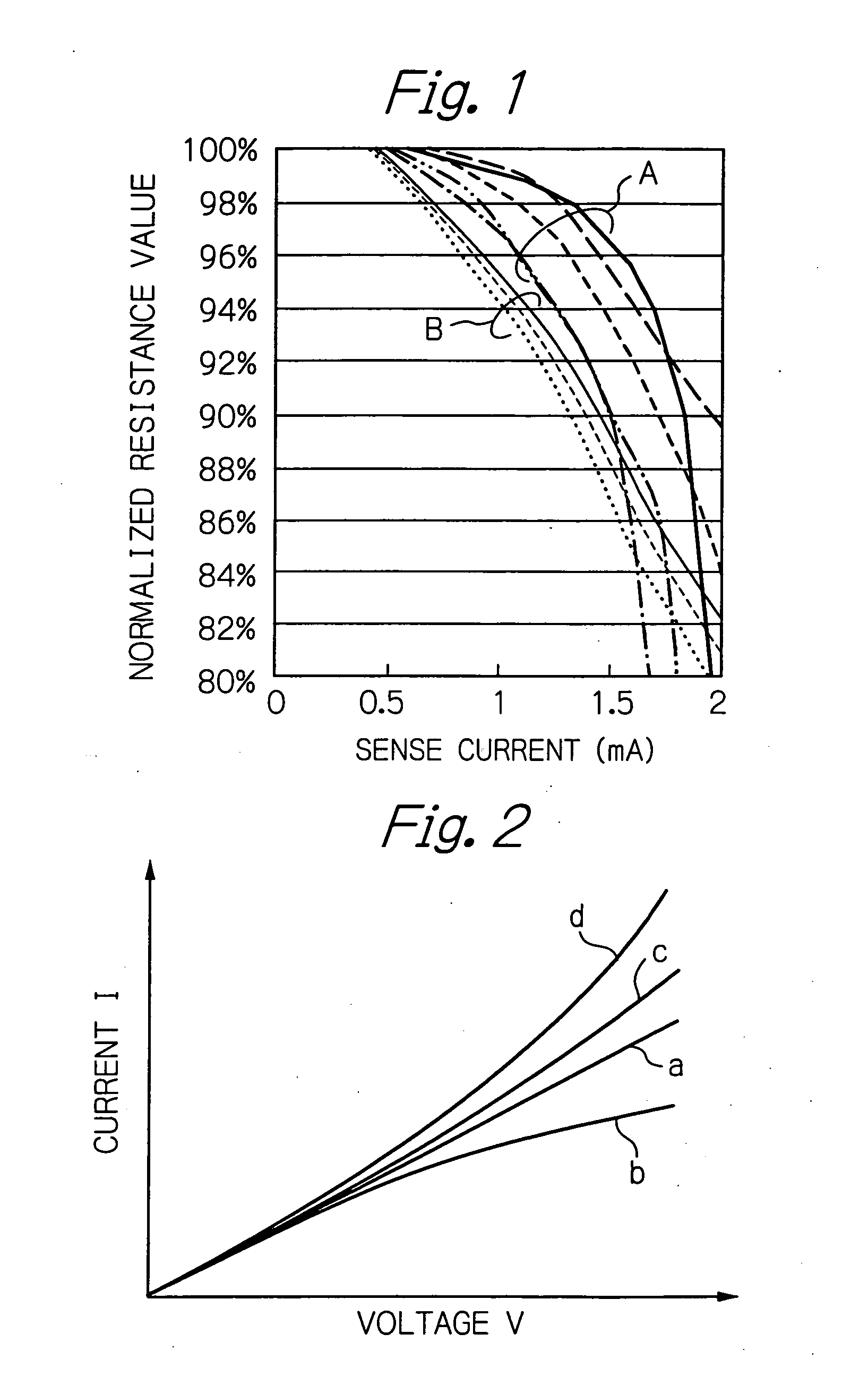
[0056]FIG. 1 illustrates characteristics of normalized resistances (%) versus sense currents Is (mA) measured by the inventors with respect to a plurality of TMR read head elements.

[0057] As will be noted from the figure, there were two groups, that is, a group A of the TMR read head elements with resistances gradually decreasing when the sense currents increased and a group B of the TMR read head elements with resistances abruptly d...


PUM

PropertyMeasurementUnit
Currentaaaaaaaaaa
Currentaaaaaaaaaa
Electrical resistanceaaaaaaaaaa

Abstract

A method for testing a TMR element includes a step of measuring a plurality of resistances of the TMR element by feeding a plurality of sense currents with different current values each other through the TMR element, a step of calculating a ratio of change in resistance from the measured plurality of resistances of the TMR element, and a step of evaluating the TMR element using the calculated ratio of change in resistance.

Description

PRIORITY CLAIM [0001] This application claims priority from Japanese patent application No. 2004-220247, filed on Jul. 28, 2004 and Japanese patent application No. 2005-081768, filed on Mar. 22, 2005, which are incorporated herein by reference. BACKGROUND OF THE INVENTION [0002] 1. Field of the Invention [0003] The present invention relates to a method and apparatus for testing a tunnel magnetoresistive effect (TMR) element such as a TMR read head element using the tunnel magnetoresistive effect or a magnetoresistive random access memory (MRAM) cell, to a manufacturing method of a TMR element, and to a TMR element. [0004] 2. Description of the Related Art [0005] An evaluation test is in general performed for determining whether or not a thin-film magnetic head with a TMR read head element is a non-defective product, during or after manufacturing the magnetic head. This evaluation test includes a reliability test for confirming that a breakdown voltage of the MR head element is suffi...

Claims


Application Information

Patent Timeline
IPC IPC(8): G11B5/03G01R33/12G11B5/127
CPCB82Y10/00B82Y25/00G01R33/093Y10T29/49021G11B5/3903G11B5/3909G11B5/455G01R33/098
Inventor HACHISUKA, NOZOMUINAGE, KENJITAKAHASHI, NORIOSHIMIZU, TATSUSHIWONG, PAK KIN
Owner TDK CORPARATION
Why Eureka
Try Eureka