Method and apparatus for testing tunnel magnetoresistive effect element, manufacturing method of tunnel magnetoresistive effect element and tunnel magnetoresistive effect element

a manufacturing method and technology of tunnel magnetoresistive effect, applied in the direction of semiconductor/solid-state device testing/measurement, magnetic bodies, instruments, etc., can solve the problems of requiring a great deal of manpower and in time for confirming reliability, and it is difficult to clearly judge whether the tmr element is good product or not with reliability, so as to achieve quick and easy confirmation of reliability of the tmr elemen

Inactive Publication Date: 2008-05-13
TDK CORPARATION
View PDF5 Cites 12 Cited by
  • Summary
  • Abstract
  • Description
  • Claims
  • Application Information

AI Technical Summary

Benefits of technology

[0010]It is therefore an object of the present invention to provide a method and apparatus for testing a TMR element, a manufacturing method of a TMR element, and a TMR element, whereby a reliability of the TMR element can be quickly and easily confirmed without failing.

Problems solved by technology

However, this testing method disclosed in U.S. Pat. No. 6,473,257 requires a performance test of the TMR read head element such as an electromagnetic conversion performance test of the TMR read head element, and thus requires a great deal of expense in manpower and in time for confirming a reliability.
However, because the ratio of change in the resistances dMRR(%) has extremely strong correlation to the resistance of the TMR element and also there are mixed influences of film area and film material, it is difficult to clearly judge whether the TMR element is good product or not with reliability.

Method used


Image

  • Method and apparatus for testing tunnel magnetoresistive effect element, manufacturing method of tunnel magnetoresistive effect element and tunnel magnetoresistive effect element
  • Method and apparatus for testing tunnel magnetoresistive effect element, manufacturing method of tunnel magnetoresistive effect element and tunnel magnetoresistive effect element
  • Method and apparatus for testing tunnel magnetoresistive effect element, manufacturing method of tunnel magnetoresistive effect element and tunnel magnetoresistive effect element

Examples


Embodiment Construction

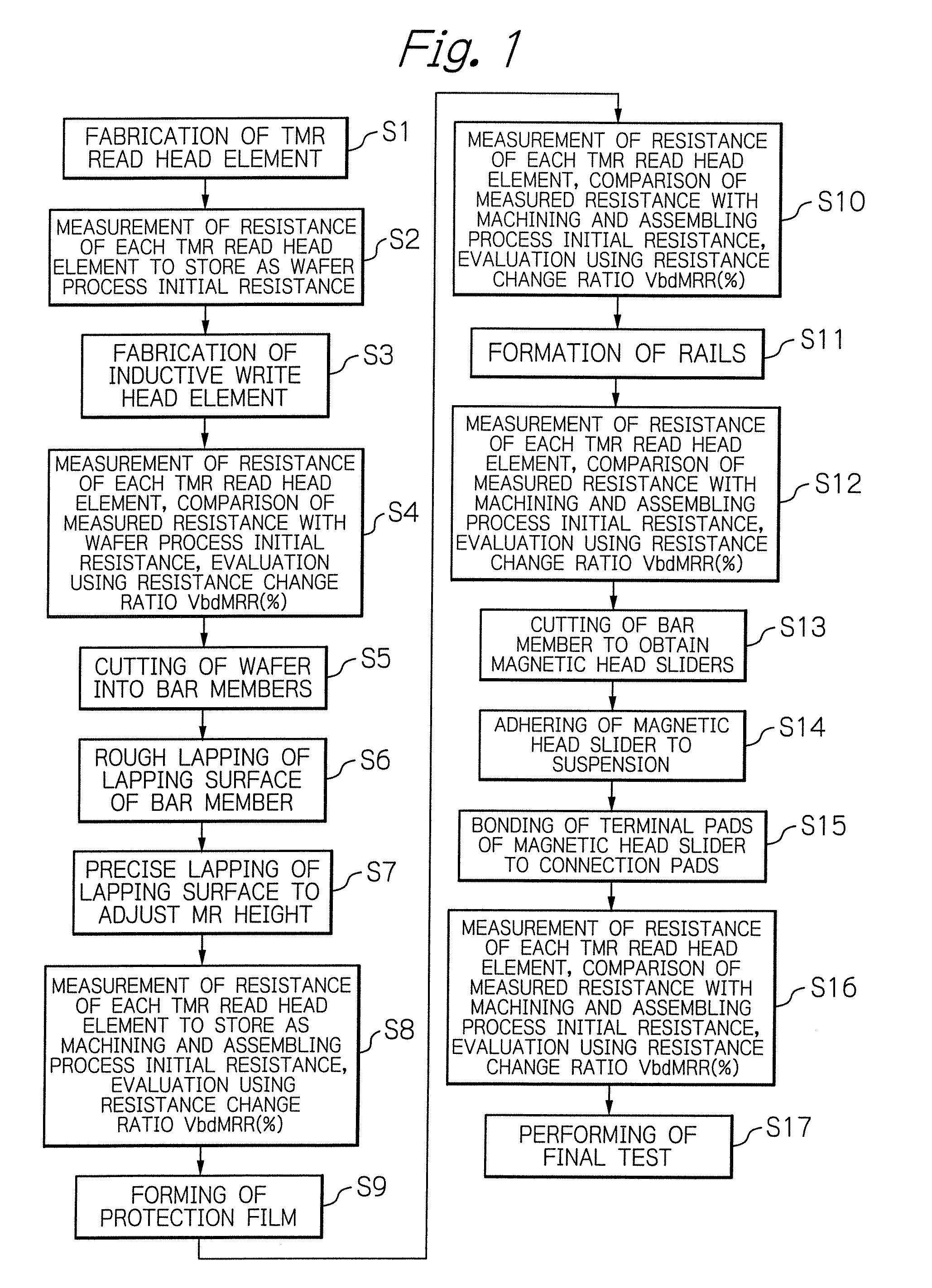
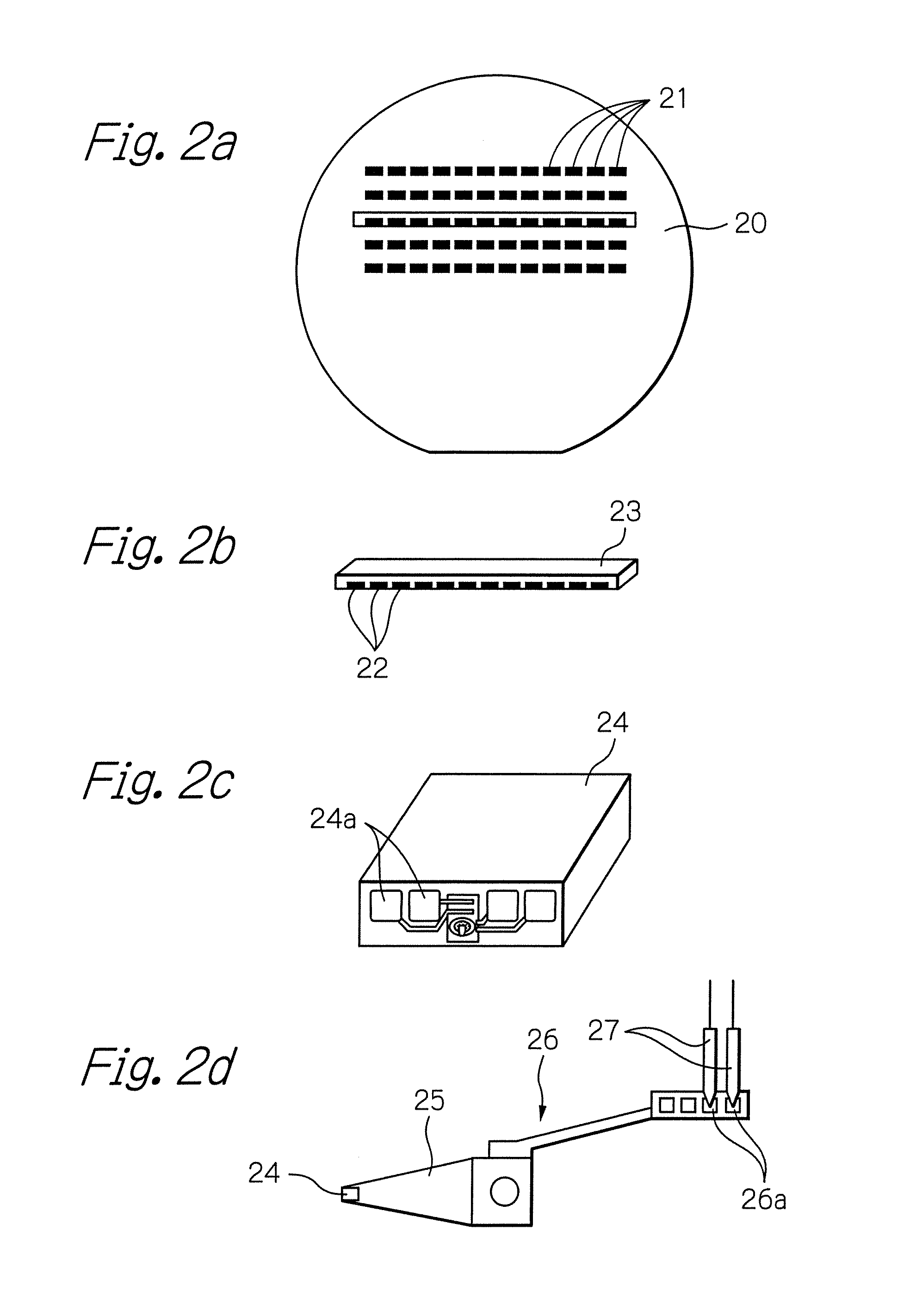
[0062]FIG. 1 schematically illustrates a wafer process for fabricating thin-film magnetic heads with TMR read head elements and an assembling process for forming HGAs as a preferred embodiment according to the present invention, and FIGS. 2a to 2d illustrate a part of the processes shown in FIG. 1.

[0063]First, many TMR read head elements such as TMR read head elements for longitudinal magnetic recording or perpendicular magnetic recording are formed in matrix on a thin-film integration surface of a wafer for thin-film (Step S1).

[0064]FIGS. 3 and 4 illustrate an example structure of each TMR read head element thus formed. FIG. 3 shows a section seen along a direction orthogonal to the ABS of the TMR read head element and FIG. 4 shows a section seen from the ABS.

[0065]As shown in FIGS. 3 and 4, a TMR film of the TMR read head element has a multilayered structure of an anti-ferromagnetic layer (pin layer) 31, a pined layer 32, a tunnel barrier layer 33, a free layer 34 and a cap layer ...


PUM


Abstract

A method for testing a TMR element includes a step of measuring a plurality of resistances of the TMR element by applying a plurality of voltages with different voltage values each other to the TMR element, respectively, a step of calculating a ratio of change in resistance from the measured plurality of resistances of the TMR element, and a step of evaluating the TMR element using the calculated ratio of change in resistance.

Description

PRIORITY CLAIM[0001]This application claims priority from Japanese patent application No.2005-088304, filed on Mar. 25, 2005, which is incorporated herein by reference.BACKGROUND OF THE INVENTION[0002]1. Field of the Invention[0003]The present invention relates to a method and apparatus for testing a tunnel magnetoresistive effect (TMR) element such as a TMR read head element using the tunnel magnetoresistive effect or a magnetoresistive random access memory (MRAM) cell, to a manufacturing method of a TMR element, and to a TMR element.[0004]2. Description of the Related Art[0005]An evaluation test of a thin-film magnetic head with a TMR read head element is in general performed for determining whether or not the thin-film magnetic head is a non-defective product, during or after manufacturing the magnetic head. This evaluation test includes a reliability test for confirming that a breakdown voltage of the TMR head element is sufficiently high to withstand an extended period of use.[...

Claims


Application Information

Patent Timeline
Patent Type & Authority Patents(United States)
IPC IPC(8): G01R27/08H01L21/66
CPCB82Y10/00B82Y25/00B82Y40/00G01R33/098G11B5/3166G11B5/3903G11B5/3909G11B5/455G11C11/16G11C29/50G11C29/50008G11C29/56H01F10/3254H01F41/302
Inventor HACHISUKA, NOZOMUKIYONO, HIROSHIKAGAMI, TAKEOINAGE, KENJITAKAHASHI, NORIO
Owner TDK CORPARATION
Why Eureka
Try Eureka