Method and apparatus for testing tunnel magnetoresistive effect element, manufacturing method of tunnel magnetoresistive effect element and tunnel magnetoresistive effect element

a manufacturing method and technology of tunnel magnetoresistive effect, applied in the direction of functional testing of recording heads, semiconductor/solid-state device testing/measurement, instruments, etc., can solve the problems of requiring a great deal of manpower and in time for confirming reliability, and achieve the effect of quick and easy confirmation of reliability of tmr elements

Active Publication Date: 2008-08-26
TDK CORPARATION +1
View PDF6 Cites 24 Cited by
  • Summary
  • Abstract
  • Description
  • Claims
  • Application Information

AI Technical Summary

Benefits of technology

[0008]It is therefore an object of the present invention to provide a method and apparatus for testing a TMR element, a manufacturing method of a TMR element, and a TMR element, whereby a reliability of the TMR element can be quickly and easily confirmed without failing.
[0013]Sense currents with different current values are fed to the TMR element and the resistances of the TMR element at the different current values are measured to calculate a ratio of change in resistance. The calculated ratio of change in resistance is used for evaluating the TMR element. This measurement, calculation and evaluation are performed for every TMR element. Element breakdown voltages of TMR elements having small ratios of change in resistance are lower than that of TMR elements having large ratios of change in resistance. Therefore, measurement of resistances by feeding sense currents with different current values and calculation of a ratio of change in resistance from thus measured resistances allow confirmation of reliability of the TMR element. Also, this evaluation test of non-defective and defective products can be extremely easily and quickly performed. Furthermore, because the evaluation test can be performed without destroying the TMR element, 100% inspection of the manufactured TMR elements becomes possible. As a result, a reliability of the TMR element can be quickly and easily confirmed without failing, and thus it is extremely effective for mass-production.
[0021]Measurement of resistances by feeding sense currents with different current values and calculation of a ratio of change in resistance from thus measured resistances allow confirmation of reliability of the TMR element. Also, the evaluation test of non-defective and defective products can be extremely easily and quickly performed. Furthermore, because the evaluation test can be performed without destroying the TMR element, 100% inspection of the manufactured TMR elements becomes possible. As a result, a reliability of the TMR element can be quickly and easily confirmed without failing, and thus it is extremely effective for mass-production.
[0031]Measurement of resistances by feeding sense currents with different current values and calculation of a ratio of change in resistance from thus measured resistances allow confirmation of reliability of the TMR element. Also, the evaluation test of non-defective and defective products can be extremely easily and quickly performed. Furthermore, because the evaluation test can be performed without destroying the TMR element, 100% inspection of the manufactured TMR elements becomes possible. As a result, a reliability of the TMR element can be quickly and easily confirmed without failing, and thus it is extremely effective for mass-production.

Problems solved by technology

However, this testing method disclosed in U.S. Pat. No. 6,473,257 requires a performance test of the TMR read head element such as an electromagnetic conversion performance test of the TMR read head element, and thus requires a great deal of expense in manpower and in time for confirming a reliability.

Method used


Image

  • Method and apparatus for testing tunnel magnetoresistive effect element, manufacturing method of tunnel magnetoresistive effect element and tunnel magnetoresistive effect element
  • Method and apparatus for testing tunnel magnetoresistive effect element, manufacturing method of tunnel magnetoresistive effect element and tunnel magnetoresistive effect element
  • Method and apparatus for testing tunnel magnetoresistive effect element, manufacturing method of tunnel magnetoresistive effect element and tunnel magnetoresistive effect element

Examples


Embodiment Construction

[0054]Before describing a preferred embodiment of the present invention, the story leading up to the present invention will be first discussed.

[0055]The inventors of this application had found that the changing characteristic in resistance of each TMR read head element differs between TMR read head elements with a predominance of metallic conduction and TMR read head elements with a predominance of tunnel current when the sense currents flowing through the TMR read head elements are increased up to a value at which the element breakdown might occur.

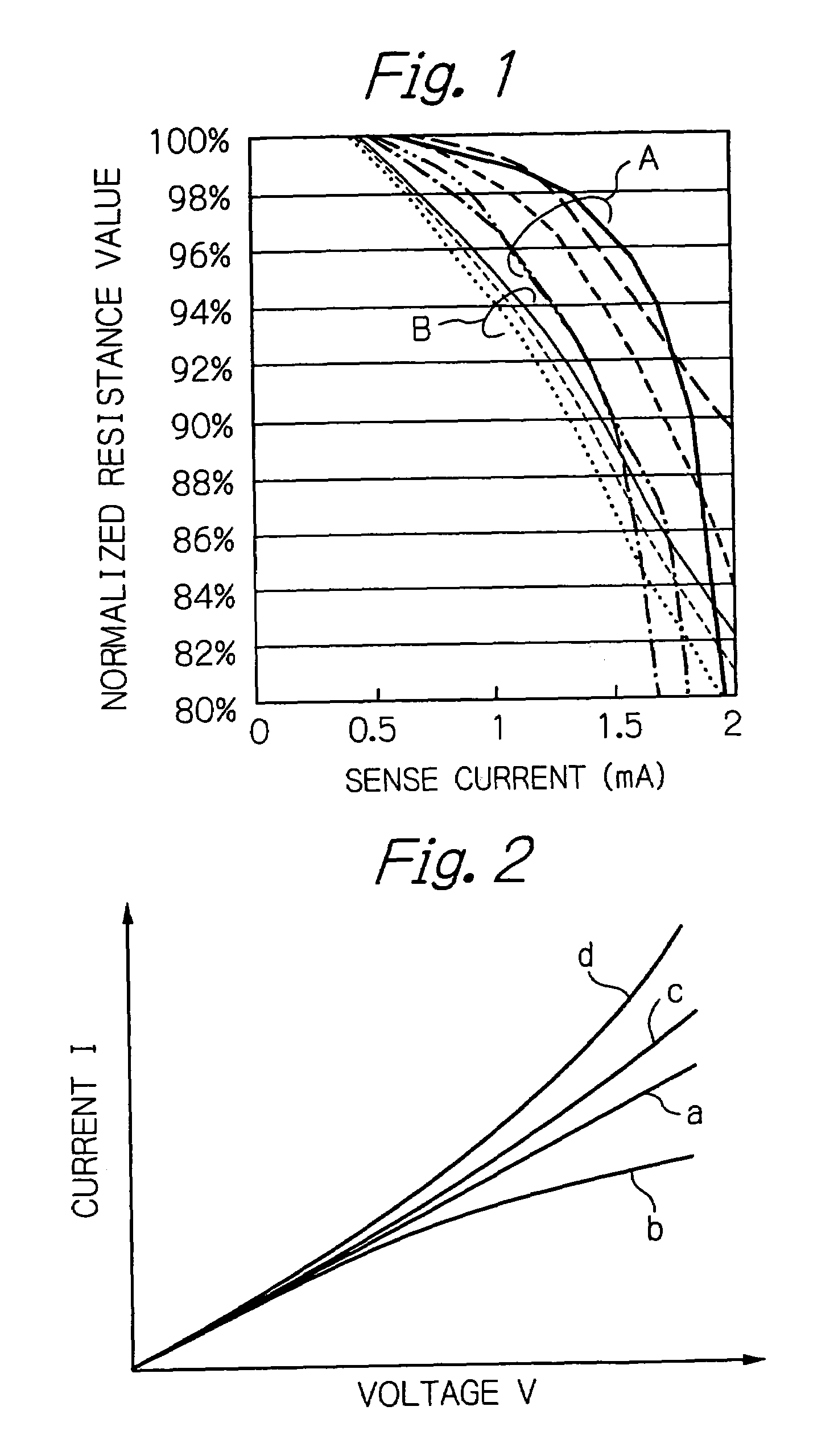
[0056]FIG. 1 illustrates characteristics of normalized resistances (%) versus sense currents Is (mA) measured by the inventors with respect to a plurality of TMR read head elements.

[0057]As will be noted from the figure, there were two groups, that is, a group B of the TMR read head elements with resistances gradually decreasing when the sense currents increased and a group A of the TMR read head elements with resistances abruptly decreas...


PUM

PropertyMeasurementUnit
currentaaaaaaaaaa
currentaaaaaaaaaa
breakdown currentaaaaaaaaaa

Abstract

A method for testing a TMR element includes a step of measuring a plurality of resistances of the TMR element by feeding a plurality of sense currents with different current values each other through the TMR element, a step of calculating a ratio of change in resistance from the measured plurality of resistances of the TMR element, and a step of evaluating the TMR element using the calculated ratio of change in resistance.

Description

PRIORITY CLAIM[0001]This application claims priority from Japanese patent application No. 2004-220247, filed on Jul. 28, 2004 and Japanese patent application No. 2005-081768, filed on Mar. 22, 2005, which are incorporated herein by reference.BACKGROUND OF THE INVENTION[0002]1. Field of the Invention[0003]The present invention relates to a method and apparatus for testing a tunnel magnetoresistive effect (TMR) element such as a TMR read head element using the tunnel magnetoresistive effect or a magnetoresistive random access memory (MRAM) cell, to a manufacturing method of a TMR element, and to a TMR element.[0004]2. Description of the Related Art[0005]An evaluation test is in general performed for determining whether or not a thin-film magnetic head with a TMR read head element is a non-defective product, during or after manufacturing the magnetic head. This evaluation test includes a reliability test for confirming that a breakdown voltage of the MR head element is sufficiently hig...

Claims


Application Information

Patent Timeline
Patent Type & Authority Patents(United States)
IPC IPC(8): G01R27/08H01L21/66
CPCB82Y10/00B82Y25/00G01R33/093G11B5/3903G11B5/3909G11B5/455G01R33/098Y10T29/49021
Inventor HACHISUKA, NOZOMUINAGE, KENJITAKAHASHI, NORIOSHIMIZU, TATSUSHIWONG, PAK KIN
Owner TDK CORPARATION
Why Eureka
Try Eureka