Ceiling fan blade attachment mechanism

a ceiling fan and blade technology, applied in the field of ceiling fans, can solve the problems of increasing the weight of the fan, increasing the cost of the fan's manufacture, and increasing the cost of the fan's purchase by the consumer

Inactive Publication Date: 2006-02-02
MINKA LIGHTING
View PDF13 Cites 44 Cited by
  • Summary
  • Abstract
  • Description
  • Claims
  • Application Information

AI Technical Summary

Problems solved by technology

The use of a conventional blade iron to attach a fan blade to a fan motor can add to the cost of the fan's manufacture and make it more expensive for purchase by a consumer.
In addition, the presence of a blade iron can add to the weight of a fan, and thereby make it less efficient from an energy consumption stand point.

Method used


Image

  • Ceiling fan blade attachment mechanism
  • Ceiling fan blade attachment mechanism
  • Ceiling fan blade attachment mechanism

Examples


Embodiment Construction

[0019] Reference will now be made in detail to embodiments of the invention, an example of which is illustrated in the accompanying drawings.

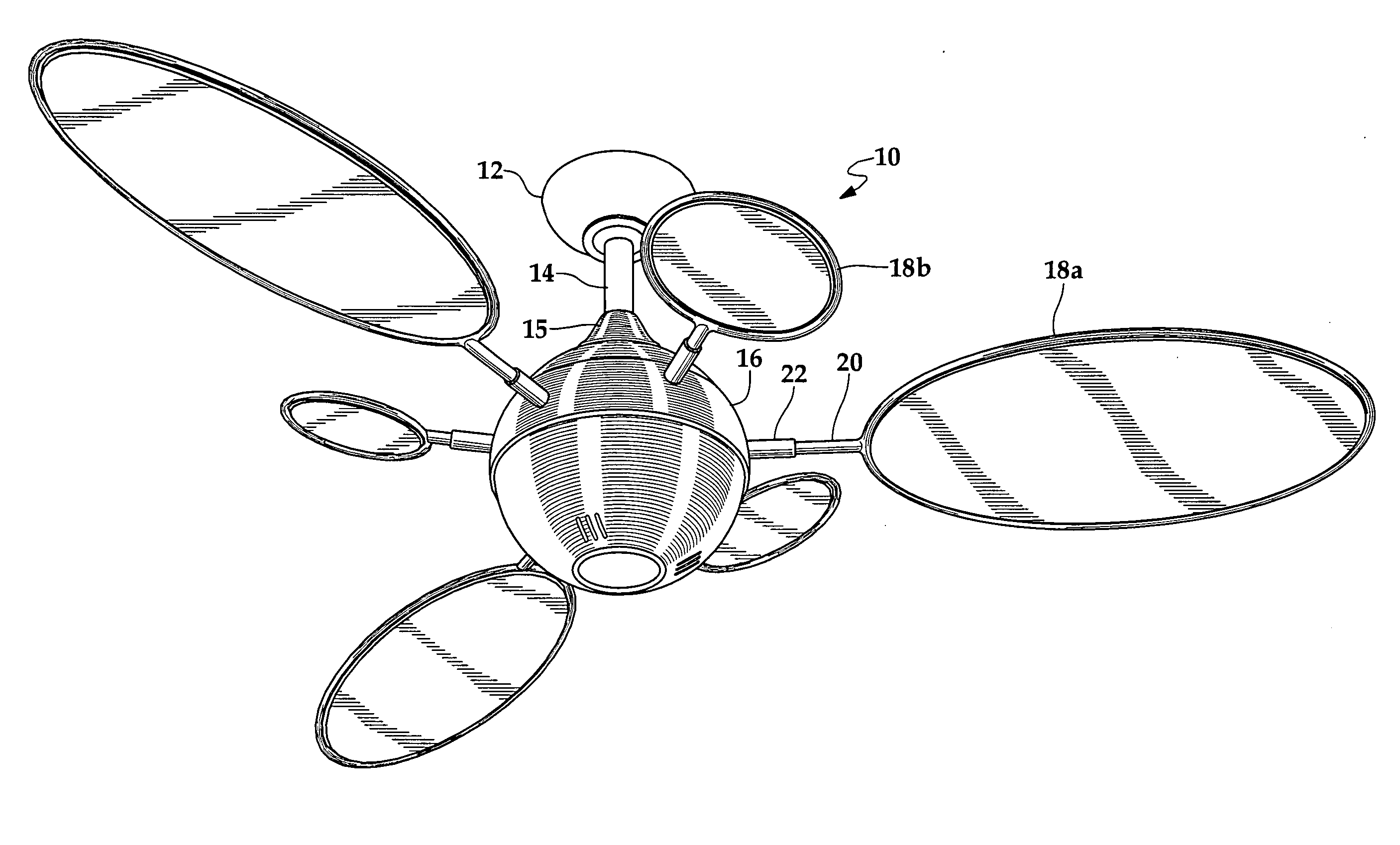
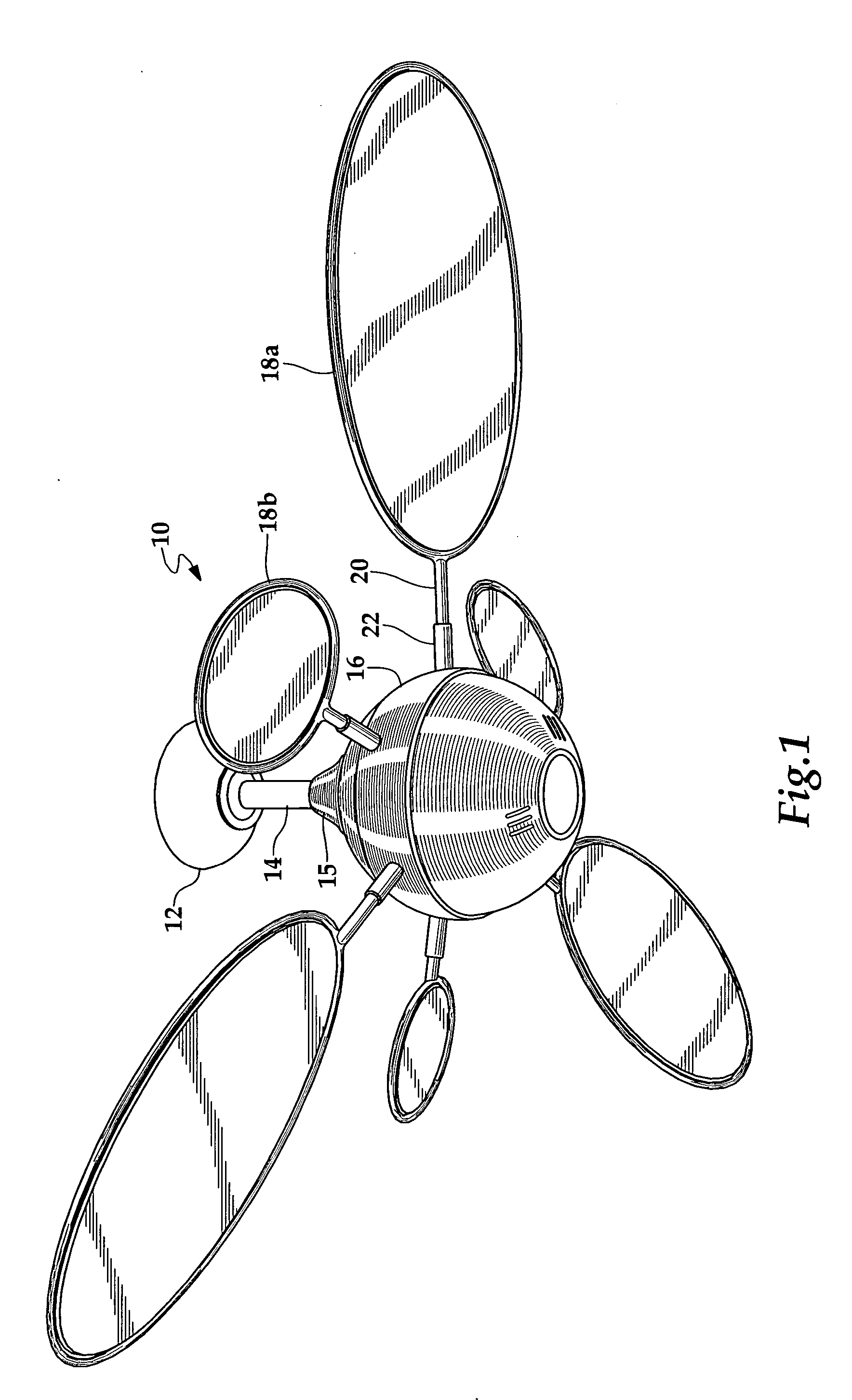
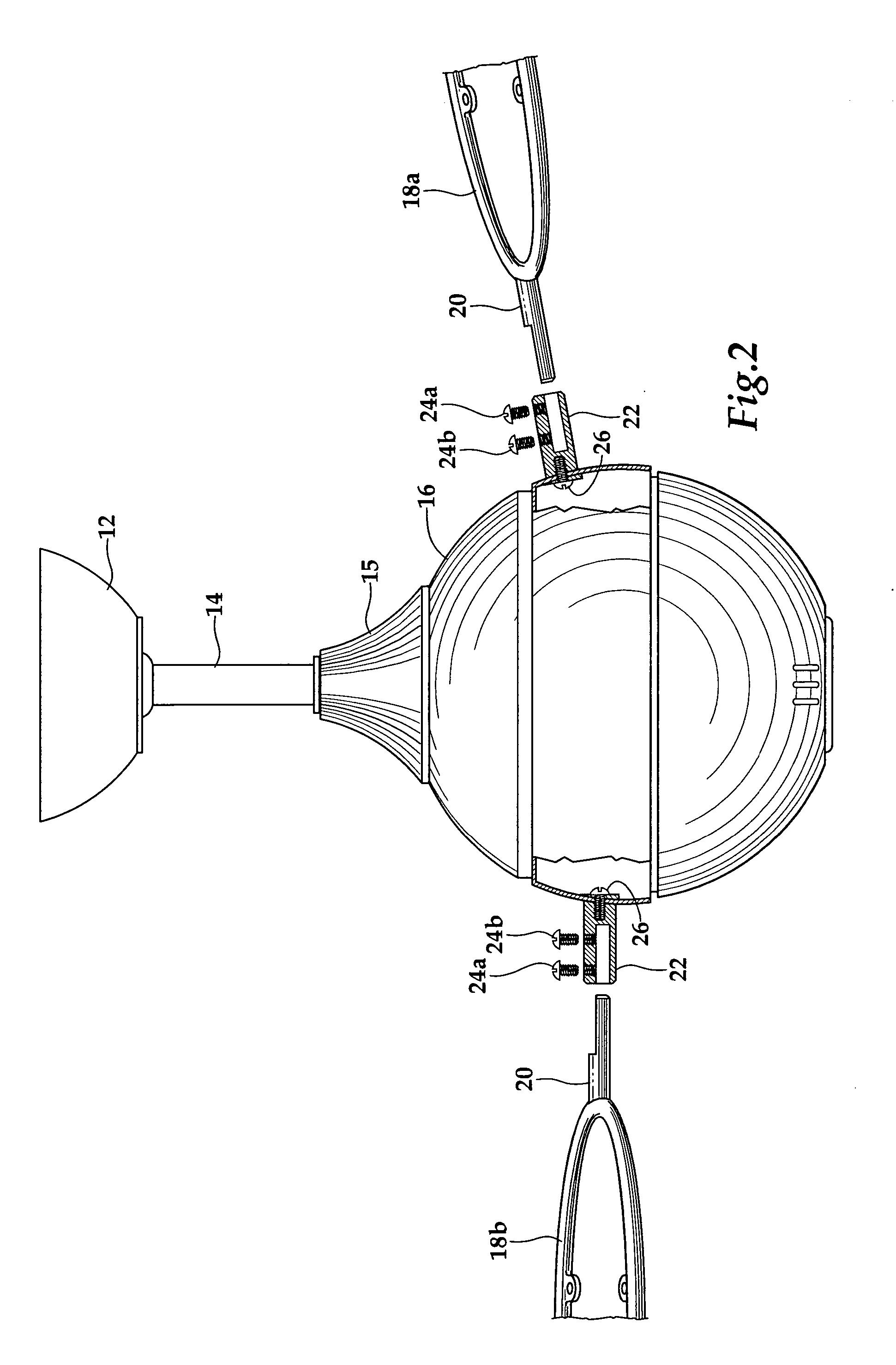
[0020] Referring to FIG. 1, the ceiling fan 10 is connected to a down rod assembly 14 that is suspended from the ceiling via a ceiling mount 12. A housing cap 15 is stationary and is typically connected to the down rod 14. A motor housing 16 is connected to the down rod 14 via the housing cap 15 and rotates relative to the down rod 14 when the ceiling fan 10 is in operation. The ceiling fan 10 includes one or more fan blades. For convenience, a plurality of fan blades will be designated by reference numbers 18a and 18b. The plurality of fan blades 18a and 18b each comprise a first attachment member 20 that facilitates the attachment of the fan blades to the motor housing 16. In certain embodiments of the invention, the first attachment member 20 is contiguous with, i.e, not separable from the rest of the fan blade structure. The attachment of ...


PUM


Abstract

The invention relates generally to fans, and in particular to ceiling fans. The invention further relates to a ceiling fan blade attachment mechanism.

Description

PRIOR RELATED APPLICATIONS [0001] This application is a continuation-in-part of application Ser. No. 29 / 210,406, filed Jul. 30, 2004, and a continuation-in part of application Ser. No. 29 / 210,460 filed Jul. 30, 2004, and a continuation-in-part of application Ser. No. 29 / 210,407 filed Jul. 30, 2004, and a continuation-in-part of application Ser. No. 29 / 210,394 filed Jul. 30, 2004, and a continuation-in-part of application Ser. No. 29 / 210,409 filed Jul. 30, 2004 and a continuation-in-part of application Ser. No. 29 / 210,391 filed Jul. 30, 2004.FEDERALLY SPONSORED RESEARCH STATEMENT [0002] Not applicable. REFERENCE TO MICROFICHE APPENDIX [0003] Not applicable. FIELD OF THE INVENTION [0004] The invention relates generally to fans, and in particular to ceiling fans. The invention further relates to a ceiling fan blade attachment mechanism. BACKGROUND OF THE INVENTION [0005] A typical ceiling fan includes a down rod assembly suspended from the ceiling with a motor shaft which is connected ...

Claims


Application Information

Patent Timeline
Patent Type & Authority Applications(United States)
IPC IPC(8): B63H1/20
CPCF04D29/34F04D25/088
Inventor GAJEWSKI, MARK
Owner MINKA LIGHTING
Why Eureka
Try Eureka