Device, System and Method for On-Line Explosive Deslagging

a technology of explosive deslagging and devices, applied in the field of boiler/furnace deslagging, can solve the problems of reducing the service life of the equipment, so as to enhance the safety and integrity of the facility, and recover valuable operation tim

Inactive Publication Date: 2006-02-09
NORTHAMERICAN IND SERVICES INC NAIS
View PDF26 Cites 5 Cited by
  • Summary
  • Abstract
  • Description
  • Claims
  • Application Information

AI Technical Summary

Benefits of technology

[0021] It is therefore desired to provide a device, system and method whereby explosives may be used to clean a boiler, furnace, scrubber, or any other heat exchange device, fuel burning, or incinerating device, without requiring that device to be shut down, thereby enabling that device to remain in full operation during des...

Problems solved by technology

But the process is costly, since the boiler must be shut down (i.e. brought off line) in order to perform this type of cleaning, and valuable production time is thereby lost.
This lost time is not only the time during which the cleaning process is being performed.
Also lost are several hours prior to cleaning when the boiler must be taken off line to cool down, and several hours subsequent to cleaning for the boiler to be restarted and brought into full operational capacity.
Were the boiler to remain on-line during cleaning, the immense heat of the boiler would prematurely detonate any explosive placed into the boiler, before the explosive has been properly positioned for detonation, rendering the process ineffective and possibly damaging the boiler.
Worse, loss of control over the precise timing of detonation would create a serious danger for personnel located near the boiler at the time of detonation.
But in all of these disclosures, the essential problem remains.
If the boiler were to remain on-line during deslagging, the heat of the boiler would cause the explosive to prematurely detonate before it is properly placed, and this uncontrolled explosion will not be effective, may damage the boiler, and could cause serious injury to personnel.
Second, the method disclosed by this patent is dangerous, and must be performed quickly to avoid danger.
1, lines 49-51) Not only is the process of draining the pipe and readying it to receive the explosive fairly cumb...

Method used


Image

  • Device, System and Method for On-Line Explosive Deslagging
  • Device, System and Method for On-Line Explosive Deslagging
  • Device, System and Method for On-Line Explosive Deslagging

Examples


Embodiment Construction

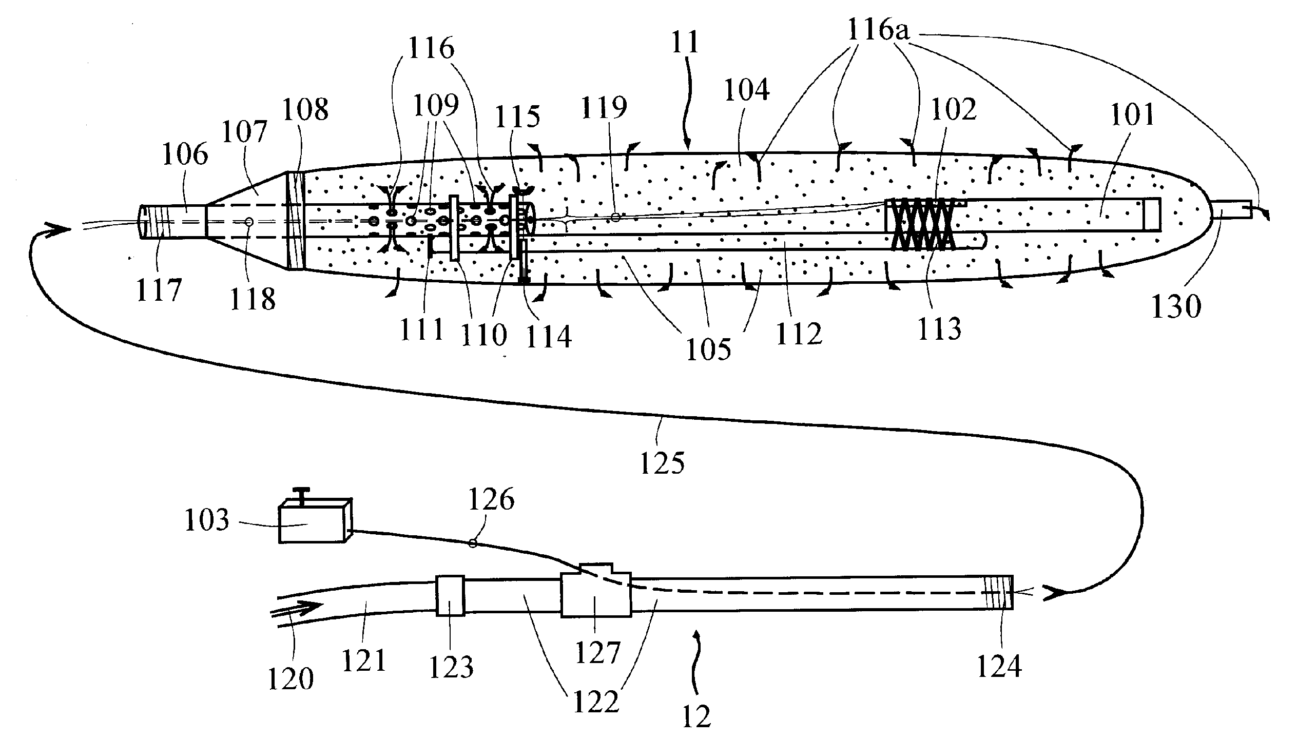
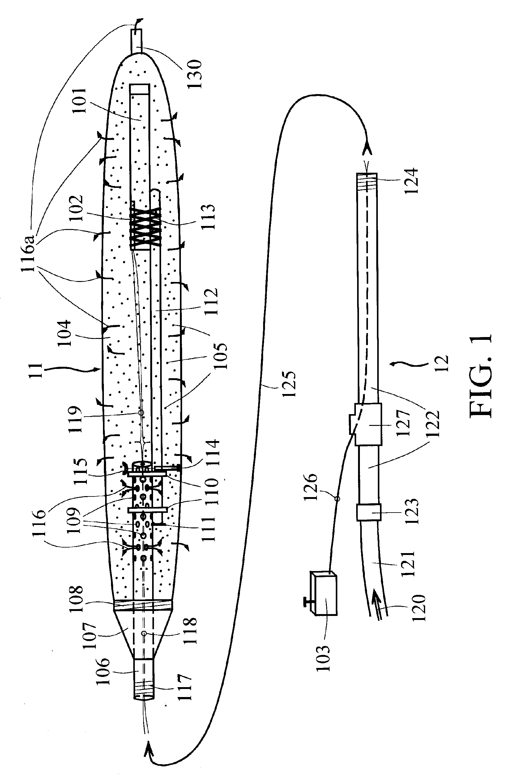
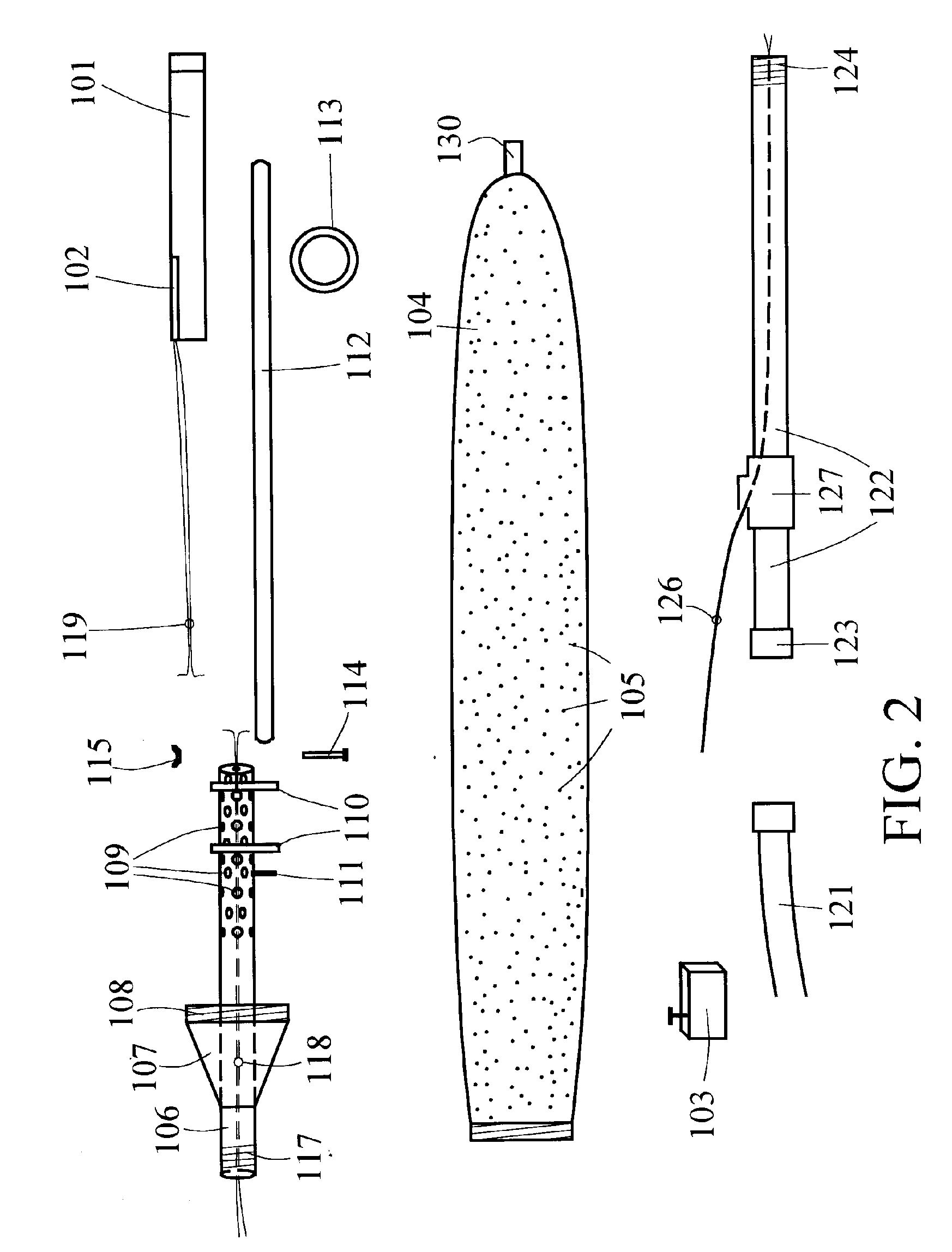
[0032]FIG. 1 depicts the basic tool used for on-line cleaning of a fuel-burning facility such as a boiler, furnace, or similar heat exchange device, or an incineration device, and the discussion following outlines the associated method for such on-line cleaning.

[0033] The cleaning of the fuel burning and / or incineration facility is carried out in the usual manner by means of an explosive device 101, such as but not limited to an explosive stick or other explosive device or configuration, placed appropriately inside the facility, and then detonated such that the shock waves from the explosion will cause slag and similar deposits to dislodge from the walls, tubing, etc. of the facility. This explosive device 101 is detonated by a standard explosive cap 102 or similar detonating device, which causes controlled detonation at the desired instant, based on a signal sent from a standard initiator 103, by a qualified operator.

[0034] However, to enable explosives-based cleaning to be perfo...


PUM


Abstract

A device, system and method permitting on-line explosives-based cleaning and deslagging of a fuel burning facility (31) such as a boiler, furnace, incinerator, or scrubber. A coolant, such as ordinary water, is delivered to the explosives (101) to prevent them from detonating due to the heat of the on-line facility. Thus, controlled, appropriately-timed detonation can be initiated as desired, and boiler scale and slag is removed without the need to shut down or cool down the facility.

Description

CROSS REFERENCE TO RELATED APPLICATIONS [0001] This application is a divisional of pending U.S. application Ser. No. 10 / 604,631 filed Aug. 6, 2003, which in turn is a continuation of U.S. application Ser. No. 10 / 064,730 filed Aug. 12, 2002, now U.S. Pat. No. 6,604,468 issued Aug. 12, 2003, which in turn is a continuation of U.S. application Ser. No. 09 / 341,395 filed Jul. 8, 1999, now U.S. Pat. No. 6,431,073 issued Aug. 13, 2002, which is a U.S. national stage application based on PCT / US98 / 00718 filed Jan. 14, 1998. U.S. Ser. No. 09 / 341,395 is in turn is a continuation of U.S. application Ser. No. 08 / 786,096 filed Jan. 17, 1997, now U.S. Pat. No. 5,769,034 issued Jun. 23, 1998.BACKGROUND OF INVENTION [0002] This disclosure relates generally to the field of boiler / furnace deslagging, and particularly, discloses a device, system and method allowing on-line, explosives-based deslagging. [0003] A variety of devices and methods are used to clean slag and similar deposits from boilers, fur...

Claims


Application Information

Patent Timeline
IPC IPC(8): F02D7/00B08B7/00B08B9/08F23J3/02F27D1/12F27D1/16F27D9/00F27D25/00F28G7/00F28G13/00
CPCB08B7/0007B08B9/08F22B37/486F22B37/56F23J3/02F28G7/005F27D1/12F27D1/1694F27D9/00F27D25/006F28G7/00F23J3/023
Inventor ZILKA, FRANCISZILKA, TIMOTHYPROUTY, KURTHOWARD, DONALD
Owner NORTHAMERICAN IND SERVICES INC NAIS
Why Eureka
Try Eureka