Throttle valve

a valve body and valve body technology, applied in valve arrangements, machines/engines, engine controllers, etc., can solve the problems of worsening gas mileage, achieve the effect of suppressing the air eddies of turbulent airflow, suppressing small air eddies, and suppressing airflow nois

Inactive Publication Date: 2006-02-09
NISSAN MOTOR CO LTD
View PDF8 Cites 2 Cited by
  • Summary
  • Abstract
  • Description
  • Claims
  • Application Information

AI Technical Summary

Benefits of technology

[0007] According to at least one embodiment of the present invention, since a position where an air eddy is generated by the intake air which passes through near the first end surface is different from a position where an air eddy is generated by the intake air which passes through near the second end surface, the timing of air eddies occurrences varies. Thus, it is possible to suppress the air eddies of the turbulent airflow generated in the downstream side of the valve body so as to produce relatively small air eddies. Therefore, airflow noises can also be suppressed so as to become small, without increasing the airflow resistance.

Problems solved by technology

However, in the above-mentioned conventional technology, these straightening vanes serve as airflow resistance to the intake air, which is a factor of lowering the maximum output of the engine and of worsening the gas mileage.

Method used


Image

  • Throttle valve
  • Throttle valve
  • Throttle valve

Examples


embodiment 1

[0037] First, the structure of a throttle valve according to Embodiment 1 of the present invention will be described below.

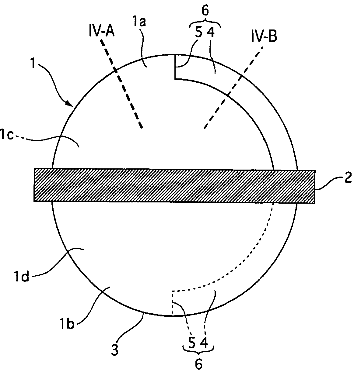
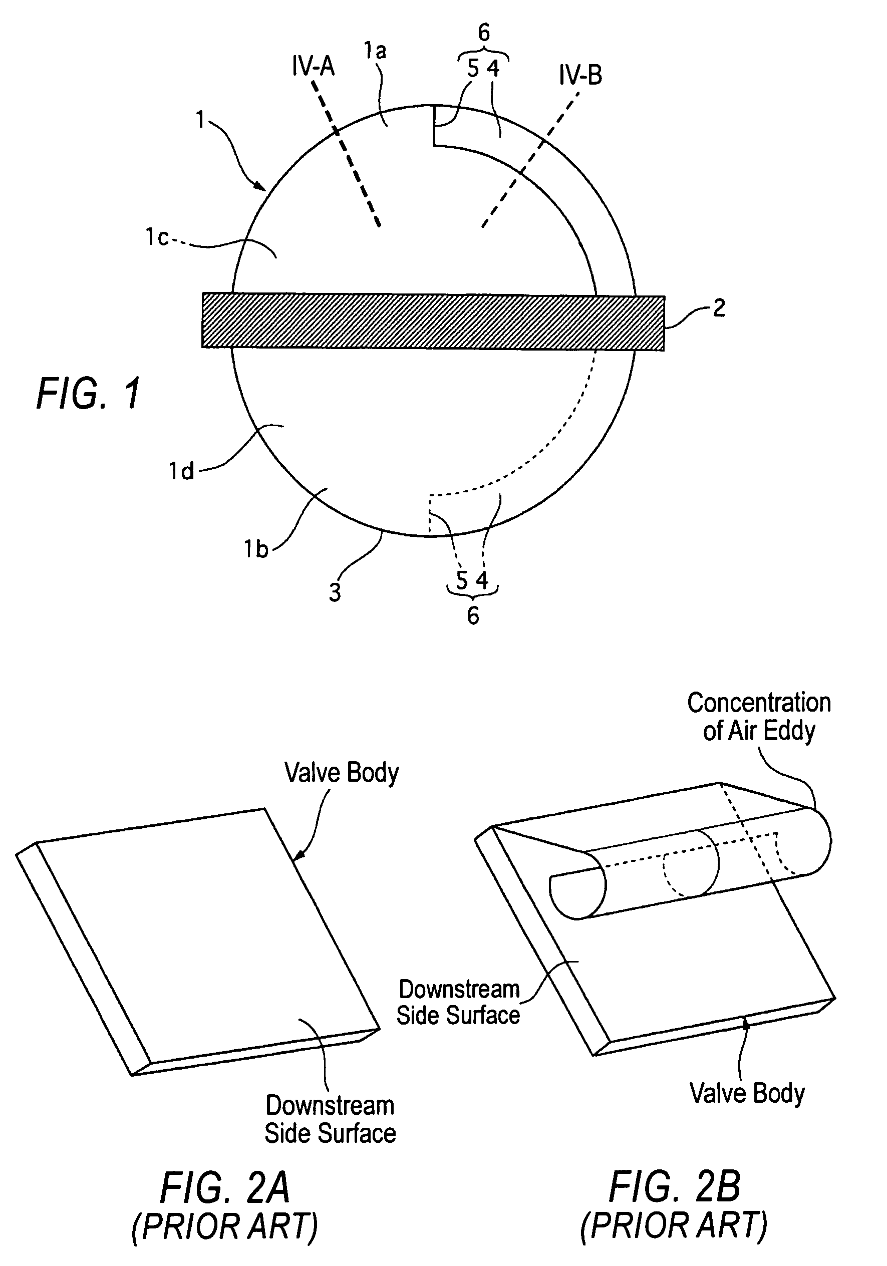
[0038]FIG. 1 illustrates the structure of a valve body 1 of the throttle valve, which is viewed from an engine side of an intake air passage.

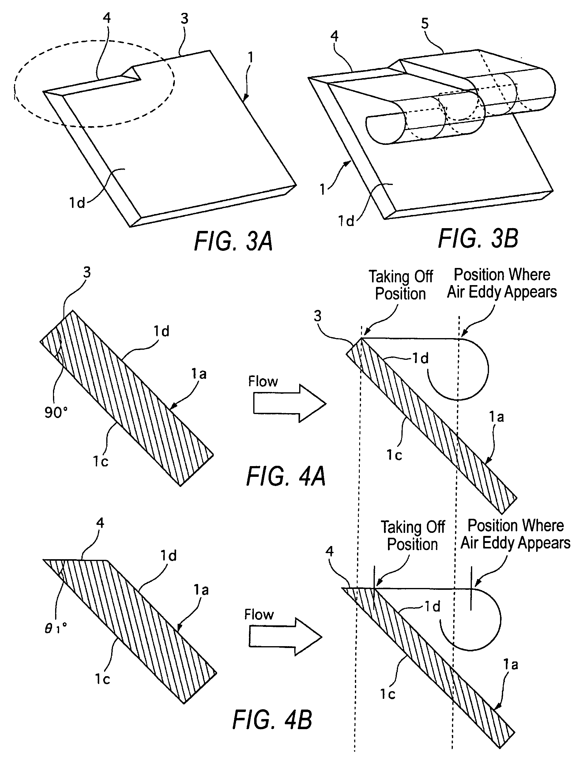
[0039] As shown in FIG. 1, the butterfly type valve body 1 is formed in the shape of a disk which corresponds to the shape of the intake air passage (not shown), and has a downstream side (engine side) surface 1d, an upstream side (air cleaner side) surface 1c (which is in back of the downstream side surface in this embodiment), an outer circumferential surface 3 which is formed perpendicular to these two surfaces, and a rotational axis 2. The upstream surface 1c and the down stream surface 1d are generally parallel to each other. The angles formed by the outer circumferential surface 3 and these two surface 1c and 1d, respectively, are not limited to 90 degrees as long as an angle formed by a first end surface (such as t...

embodiment 2

[0057] In Embodiment 2 of the present invention, as shown in FIG. 6, a second end surface 4 is formed near the outer circumference end surface in approximately the center of the outer circumferential portion of the valve body 12 in the rotational axis extending direction, and first end surfaces 3 are formed on both sides of the second end surface 4.

[0058]FIG. 6 illustrates the valve body 12 of the throttle valve according to the Embodiment 2 of the present invention, wherein the second end surface 4 is formed in the center portion of the valve body 12, and the first end surfaces 3 are formed in the left and right sides of the second end surface 4 so as to sandwich the second end surface 4 therebetween.

[0059] Next, operation of Embodiment 2 of the present invention will be described below.

[0060] In Embodiment 2 of the present invention, in the upper and lower portions 1a and 1b of the valve body 12, taking off positions of streamlines in contact with the first end surfaces 3 forme...

embodiment 3

[0065] In Embodiment 3 of the present invention, as shown in FIG. 7, a first end surface 3 is formed in a center portion of a valve body 13 in the rotational axis extending direction, and second end surfaces 4 are formed on both sides of the first end surface 3.

[0066]FIG. 7 illustrates the valve body 13 of the throttle valve according to the Embodiment 3 of the present invention, wherein the first end surface 3 is formed in the center of the outer circumferential portion of the valve body 13, and the second end surfaces 4 are formed on left and right half sides of the valve body 13 so as to sandwich the first end surface 3 between the second end surfaces 4.

[0067] Next, an operation of Embodiment 3 of the present invention will be described below.

[0068] In Embodiment 3 of the present invention, in the upper and lower portions 1a and 1b of the valve body 13, taking off positions of streamlines in contact with the two second end surfaces 4 provided on both sides of the first end sur...


PUM


Abstract

A valve body or a throttle valve is disclosed that is capable of changing the amount of intake air into an engine according to a gradient angle of a valve body rotatably supported in an intake air passage. The valve body includes at least one first end surface and at least one second end surface formed on an outer circumferential surface thereof. Air eddies occurring from air flow contact with the first and second end surfaces are shifted to each other.

Description

BACKGROUND OF THE INVENTION [0001] 1. Field of the Invention [0002] The present invention relates to a throttle valve capable of changing the amount of intake air into an engine. [0003] 2. Description of the Related Art [0004] In a conventional throttle valve, as shown in FIG. 23, an air eddy of turbulent airflow which occurs downstream of a valve body is controlled to become small, so that airflow noises are suppressed, by two or more straightening vanes which straighten the intake air on the downstream side surface of the valve body. These straightening vanes are fan-shaped in a cross sectional view and disposed in parallel at an equal interval in a rotational axis extending direction, wherein the vanes are disposed on the valve body so as to be perpendicular to the rotational axis. For a further description of the straightening vanes, refer to, for example, Japanese Laid Open Patent No. 2000-204975. [0005] However, in the above-mentioned conventional technology, these straighteni...

Claims


Application Information

Patent Timeline
Patent Type & Authority Applications(United States)
IPC IPC(8): F02D9/08F16K1/22
CPCF02D9/08F16K1/2261F02D9/1015
Inventor SAKAI, YUUKI
Owner NISSAN MOTOR CO LTD
Why Eureka
Try Eureka