Gas turbine engine vortex suppressor

a technology of gas turbine engines and suppressors, which is applied in the field of aircraft engines, can solve the problems of undesirable ground vortex formation, deterioration of fan flow quality, and difficulty in establishing ground vortex of this kind, and achieve the effect of suppressing the vortex flow

Inactive Publication Date: 2019-04-18
ROLLS ROYCE PLC
View PDF0 Cites 2 Cited by
  • Summary
  • Abstract
  • Description
  • Claims
  • Application Information

AI Technical Summary

Benefits of technology

[0015]According to the present disclosure there is provided an intake for a gas turbine engine comprising an annular lip structure extending about a central axis and defining an intake opening, the annular lip structure having a leading edge located between a radially inwardly facing portion of the intake and a radially outwardly facing portion of the intake, the annular lip structure having upper, lower and opposing side regions on either side of the central axis, wherein the annular lip structure comprises a formation on the radially inwardly facing portion arranged to create a non-symmetric flow field over the opposing side regions of the annular lip structure. The formation may act to suppress vortical flow within a working gas flow entering the intake, in use.
[0017]The formation may cause non-symmetric fluid dynamic loading of the opposing side regions of the annular lip structure. The formation may modify the load distribution on the intake lip by causing an offset of fluid dynamic loading between the opposing side regions, e.g. for an asymmetric intake flow profile—such as for a cross wind scenario.
[0018]The formation may act to suppress ground vortex formation. The formation may act to suppress ground vortex formation when the intake is located in the vicinity of the ground or another support surface, e.g. located beneath the intake / engine.

Problems solved by technology

It is a known problem that aircraft engines operating close to the ground can cause the device of a vortex externally of the engine and upstream of the engine intake.
Ground vortices are a problem especially when the engine is operating at high power / thrust while the aircraft is moving at slow speed—as an example, when taxiing—or else is static.
Establishing a ground vortex of this kind is undesirable because it deteriorates the quality of the flow into the fan.
More precisely, the ground vortex is a cause of increased fan forcing and can lead to fan stall.
In severe cases it is possible that the flow field distortion can significantly impact the flow through the core engine leading to a possibility of engine surge.
The interaction of the vortex with the ground also means that foreign objects, such as debris, can become entrained in the airflow, drawn up into the inlet and ingested by the engine.
Whilst the problems described above affect engines on the airframe, e.g. engines on wing, the same problems can arise for statically mounted engines, such as engine test beds.
However, the airflow required to achieve these aims is relatively large and the plumbing to take air from the rear compressor stages adds unwanted complexity to the engine.
Moreover the large amount of air ejected through the nozzles can adversely affect flow into the engine, e.g. the stream tube ingest of the intake.
The nozzles used in the prior art also affect fluid dynamics for the engine in normal use (i.e. away from the ground) and negatively disrupt the desired flow field for the engine intake or exterior of the nacelle when not needed.
However, the use of a separate portable device of this kind is suitable only for a testing environment and is not practical for use at airports or when aircraft are moving, e.g. taxiing.
The formation may cause non-symmetric fluid dynamic loading of the opposing side regions of the annular lip structure.
The formation may disturb or affect the flow over either or both side region.

Method used


Image

  • Gas turbine engine vortex suppressor
  • Gas turbine engine vortex suppressor
  • Gas turbine engine vortex suppressor

Examples


Embodiment Construction

[0048]Unlike the above-mentioned prior art systems that require use of an accessory external of the engine to achieve this aim, the present disclosure indicates that this can be achieved using a different, and more pragmatic, mechanism. The mechanism identified by the inventors involves modifying the fluid dynamic load of the intake flow on the engine intake lip.

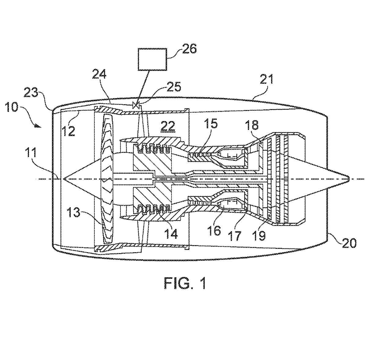
[0049]With reference to FIG. 1, a gas turbine engine is generally indicated at 10, having a principal and rotational axis 11. The engine 10 comprises, in axial flow series, an air intake 12, a propulsive fan 13, an intermediate pressure compressor 14, a high-pressure compressor 15, combustion equipment 16, a high-pressure turbine 17, an intermediate pressure turbine 18, a low-pressure turbine 19 and an exhaust nozzle 20. A nacelle 21 generally surrounds the engine 10 and defines both the intake 12 and the exhaust nozzle 20.

[0050]The gas turbine engine 10 works in the conventional manner so that a working gas such as air ente...


PUM


Abstract

An intake (12) for a gas turbine engine (10) has an annular lip structure (23) extending about a central axis (11) and defining an intake opening. The annular lip structure (23) has a leading edge (38) located between a radially inwardly facing portion of the intake and a radially outwardly facing portion of the intake (12). The annular lip structure (23) has upper, lower and opposing side regions on either side of the central axis (11). The annular lip structure (23) comprises a formation (40; 42; 48) on the radially inwardly facing portion arranged to create a non-symmetric flow field over the opposing side regions of the annular lip structure (23). The formation (40; 42; 48) may be actively controlled in response to ground vortex conditions.

Description

CROSS-REFERENCE TO RELATED APPLICATIONS[0001]This specification is based upon and claims the benefit of priority from UK Patent Application Number GB1716836.0 filed on Oct. 13, 2017, the entire contents of which are incorporated herein by reference.BACKGROUNDField of the Disclosure[0002]The present disclosure concerns aircraft engines.Description of the Related Art[0003]It is a known problem that aircraft engines operating close to the ground can cause the device of a vortex externally of the engine and upstream of the engine intake. The external vortex interacting with the ground is often referred to as a ground vortex. In order for a ground vortex to form, the ratio of the air velocities at the engine intake throat and far away from the intake must be high. In this condition, the convolution of the streamlines of the ingested flow define a stream-tube interacting with the ground. Ground vortices are a problem especially when the engine is operating at high power / thrust while the a...

Claims


Application Information

Patent Timeline
Patent Type & Authority Applications(United States)
IPC IPC(8): F02C7/042F02C7/05F02C7/057
CPCF02C7/042F02C7/05F02C7/057F05D2220/323F02C7/045F05D2270/17
Inventor DI MARE, LUCABARBAROSSA, FERNANDOCARNEVALE, MAURO
Owner ROLLS ROYCE PLC
Why Eureka
Try Eureka