Method of processing formed product, and metal cope and metal drag used for the method

a technology of metal drag and formed product, which is applied in the field of processing formed products, can solve the problems of deburring and other problems, and achieve the effect of easy corresponding to various thicknesses of workpieces

Inactive Publication Date: 2006-02-09
AMADA CO LTD
View PDF19 Cites 12 Cited by
  • Summary
  • Abstract
  • Description
  • Claims
  • Application Information

AI Technical Summary

Benefits of technology

[0011] As is understood from the description mentioned above, in accordance with the present invention, it is possible to set the burr generating direction and the bending direction of the bending piece, for example, at a time of punching the outer shape of the formed product and processing a punched hole, to the back surface side, and it is possible to omit the workpiece for removing the burr generated in the formed product, whereby it is possible to solve the conventional problem mentioned above.
[0012] Further, in accordance with the structure of the upper metal mold, it is possible to execute an over-bending while taking a spring back into consideration, at a time of bending the bending piece in the downward direction.
[0013] Further, in accordance with the structure of the lower metal mold, it is possible to easily correspond to various thicknesses of the workpiece.

Problems solved by technology

Further, since a surface in a side surrounded and raised by the slit process, that is, an upper surface side of the workpiece forms an inner portion side of the formed product, and a lower surface side of the workpiece in which the burr is generated forms an outer portion side of the formed product, there is a problem that deburring is required.

Method used


Image

  • Method of processing formed product, and metal cope and metal drag used for the method
  • Method of processing formed product, and metal cope and metal drag used for the method
  • Method of processing formed product, and metal cope and metal drag used for the method

Examples


second embodiment

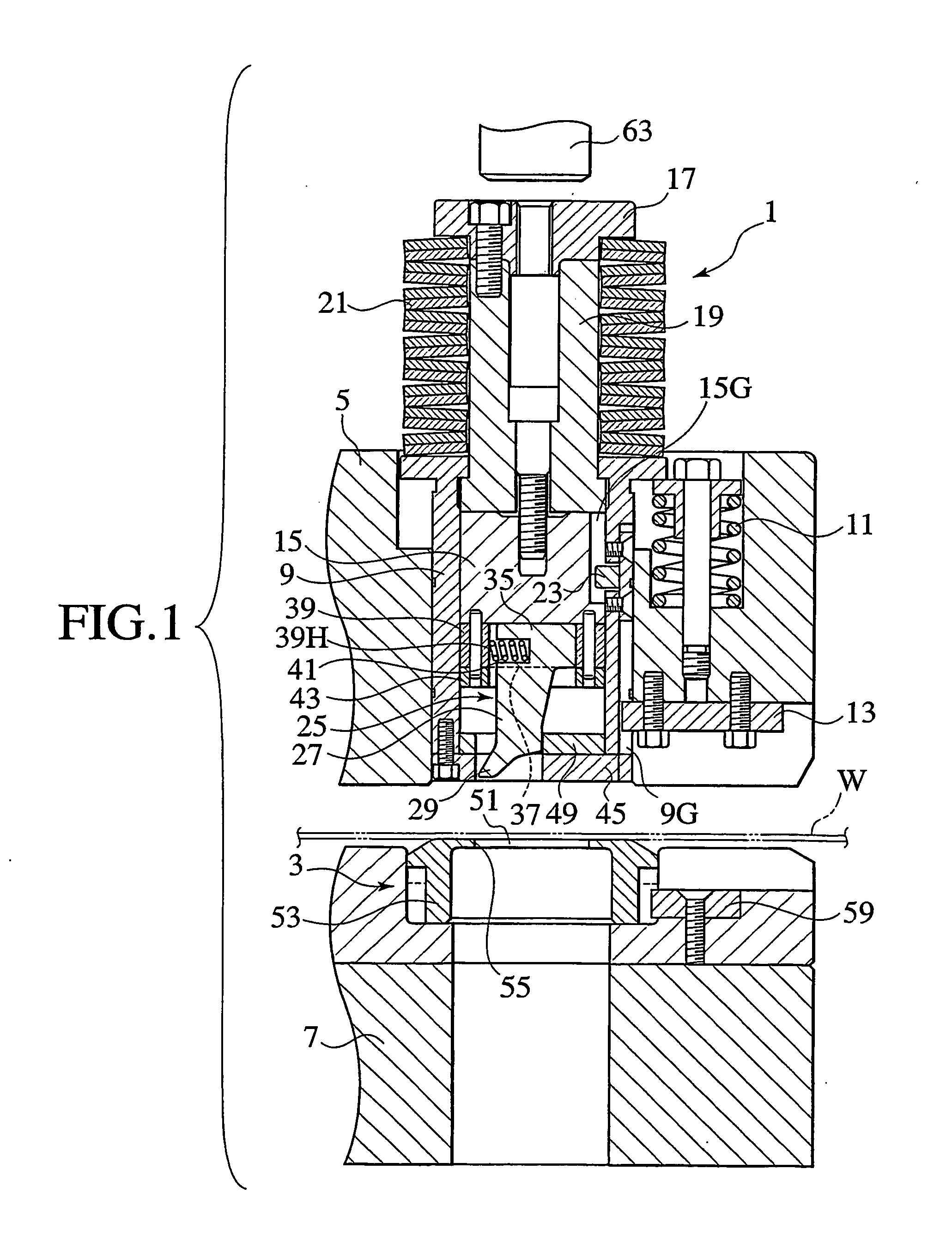
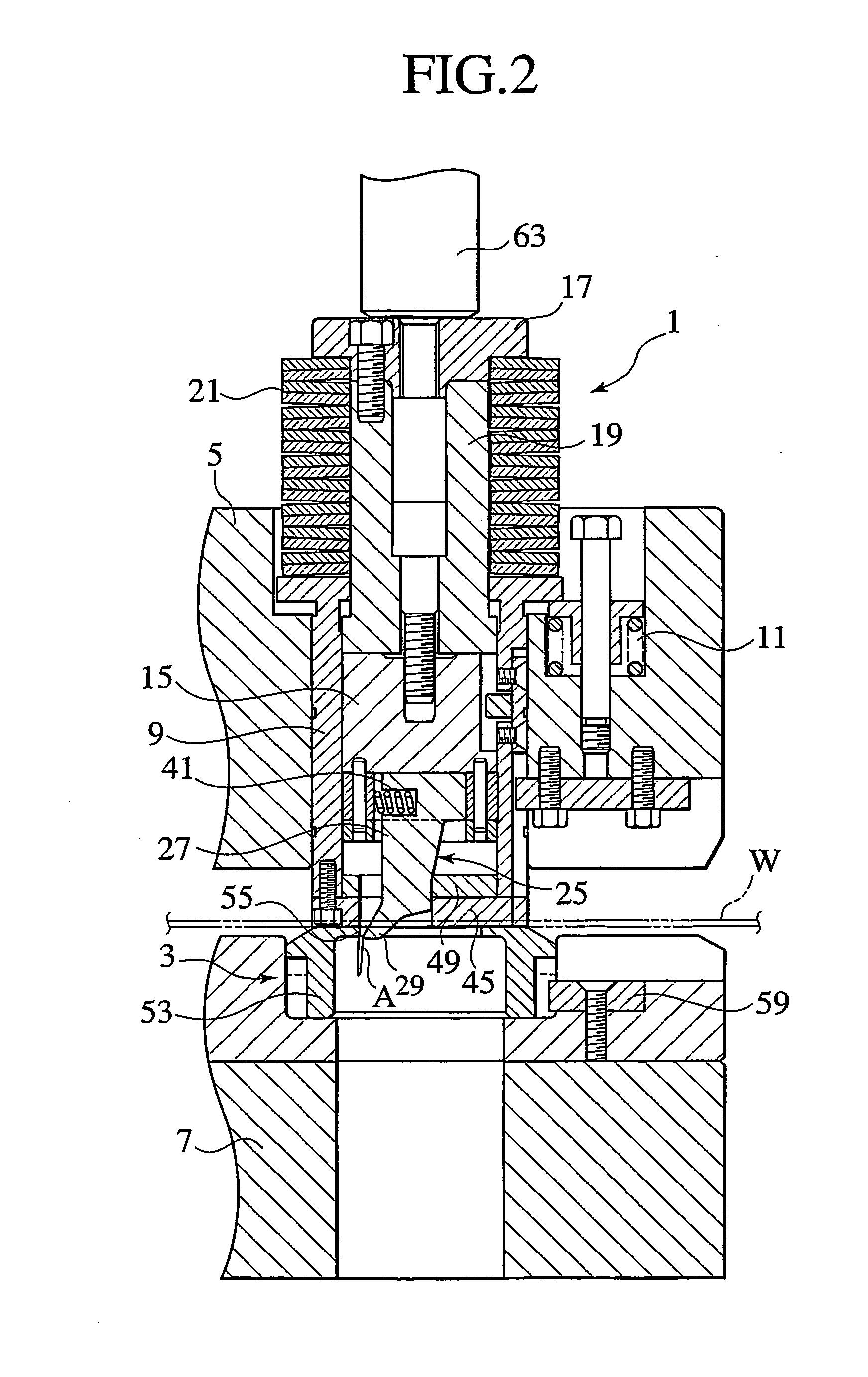
[0051] In other words, the structure may be made such that a pressing block 65 freely pressing the punch chip 25 is slidably provided, as shown in FIG. 5 showing the metal mold 1, on an upper surface of the plate presser foot 45 or a punch chip guide member 149, a wedge block 67 allowed to be pressed down by the lower surface of the support member 43 is arranged between the pressing block 65 and the inner peripheral surface of the punch guide 9 so as to be movable upward and downward, and an elastic member 69 such as a tension spring is provided in a tensional manner between the pressing block 65 and the wedge block 67, for the purpose of holding an inclined surface of the pressing block 65 and an inclined surface of the wedge block 67 in a full-time contact state.

first embodiment

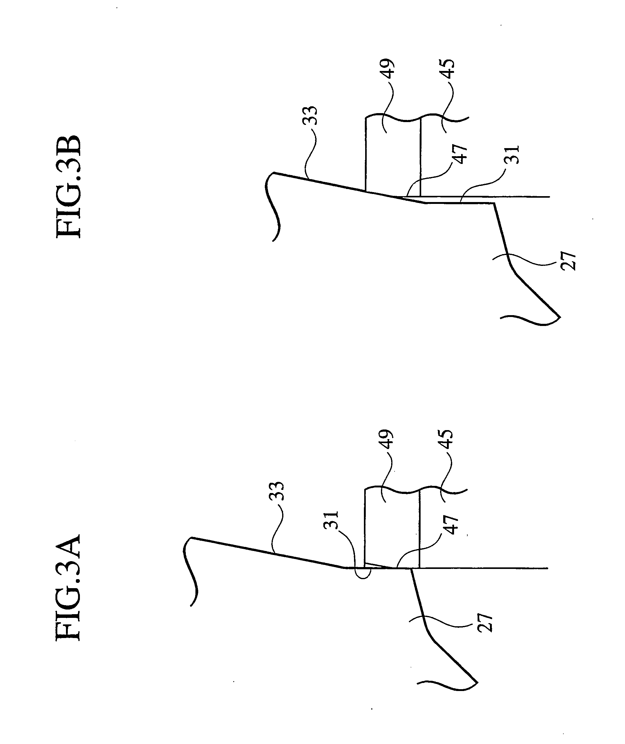
[0052] In the case of the present embodiment, an approximately vertical sliding surface 131 of the punch chip 25 is formed longer upward than the sliding surface 31 in accordance with the first embodiment mentioned above. Accordingly, even if the punch chip 25 is moved downward to a lower end position, a side surface of the punch chip guide member 149 neither is in contact with the inclined surface 33 (refer to FIG. 3B) nor slide.

[0053] In accordance with the structure mentioned above, in the case that the support member 43 fixed to the lower surface of the punch body 15 is brought into contact with the wedge block 67 so as to gradually move downward the wedge block 67 at a time of the bending process of the bending piece A of the raw material C, the pressing block 65 is gradually moved in a leftward direction in FIG. 5, and pressure moves the punch chip 25 in the leftward direction.

[0054] Therefore, in accordance with the structure mentioned above, when bending the bending piece A...


PUM

PropertyMeasurementUnit
angleaaaaaaaaaa
angleaaaaaaaaaa
bending angleaaaaaaaaaa

Abstract

A method is provided for processing a product formed by a punch press. The method includes leaving a micro joint connecting a workpiece to a raw material forming the product when forming a slit in the workpiece along an outer shape of the raw material. The method also includes forming the product by bending a bending process portion downward on the basis of a cooperation of an upper metal mold and a lower metal mold. The method further includes dropping the product by separating the connection between the product and the workpiece by the micro joint.

Description

TECHNICAL FIELD [0001] The present invention relates to a method of processing a formed product which is partly bent, for example, by a punch press, such as a turret punch press or the like, and upper and lower metal molds used for the method, and more particularly to a processing method of processing a formed product in which a bending direction of a bending piece is set to the same as a generating direction of a burr generated at a time of punching an outer shape of a product shape, and upper and lower metal molds used for the process. BACKGROUND ART [0002] In conventional, in the case of applying a bending process to a part of a workpiece by a punch press, a workpiece is moved and positioned in X and Y directions with respect to a processing position, and a slit is processed along an outer shape of a raw material forming the formed product. Further, a slit process is applied also to a periphery of a portion to be bent in a raw material forming the formed product, and a portion su...

Claims


Application Information

Patent Timeline
Patent Type & Authority Applications(United States)
IPC IPC(8): A47J36/02B21D5/00B21D5/04B21D28/10B21D28/36B21D35/00
CPCB21D5/01B21D5/04Y10T29/49792B21D35/00B21D28/10B21D5/045B21D5/00
Inventor ENDO, SHIGERU
Owner AMADA CO LTD
Why Eureka
Try Eureka