Image-forming device

a technology of image-forming device and operating mode, which is applied in the direction of electrographic process apparatus, instruments, optics, etc., can solve the problems of complicated operation of image-forming device, and inability to perform diagnosis, so as to prevent a switch in operating mode and increase the complexity of switching modes

Active Publication Date: 2006-02-16
BROTHER KOGYO KK
View PDF7 Cites 5 Cited by
  • Summary
  • Abstract
  • Description
  • Claims
  • Application Information

AI Technical Summary

Benefits of technology

[0007] In view of the foregoing, it is an object of the present invention to provide an image-forming device having a self-diagnostic function for diagnosing components of the image-forming device and that is capable of preventing a switch in operating modes due to an incorrect operation by the user, without increasing the complexity for switching modes.

Problems solved by technology

However, since the operating mode of the image-forming device described above is switched according to an external operation, if the user of the image-forming device mistakenly performs the external operation, the operating mode is switched against the user's wishes.
However, these countermeasures complicate the operations required to change the operating mode to the self-diagnostic mode.
Hence, the image-forming device can perform a diagnosis that is not possible when the image-forming cartridge is mounted in the image-forming device (such as a diagnosis that outputs a higher voltage).
Hence, the image-forming device can detect the position of the recording medium without providing new means for that purpose.

Method used


Image

  • Image-forming device
  • Image-forming device
  • Image-forming device

Examples


first embodiment

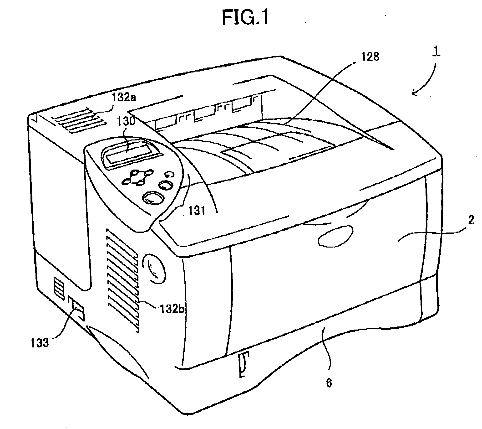
[0063]FIG. 1 is a perspective view showing a laser printer 1 according to a As shown in FIG. 1, the laser printer 1 includes a main frame 2, a paper tray 6, a discharge tray 128, ventilating holes 132a and 132b, a display unit 130 for displaying the status of the laser printer 1, an operating unit 131 for specifying operations of the laser printer 1 and the like, and a power switch 133 for switching the power of the laser printer 1 on and off.

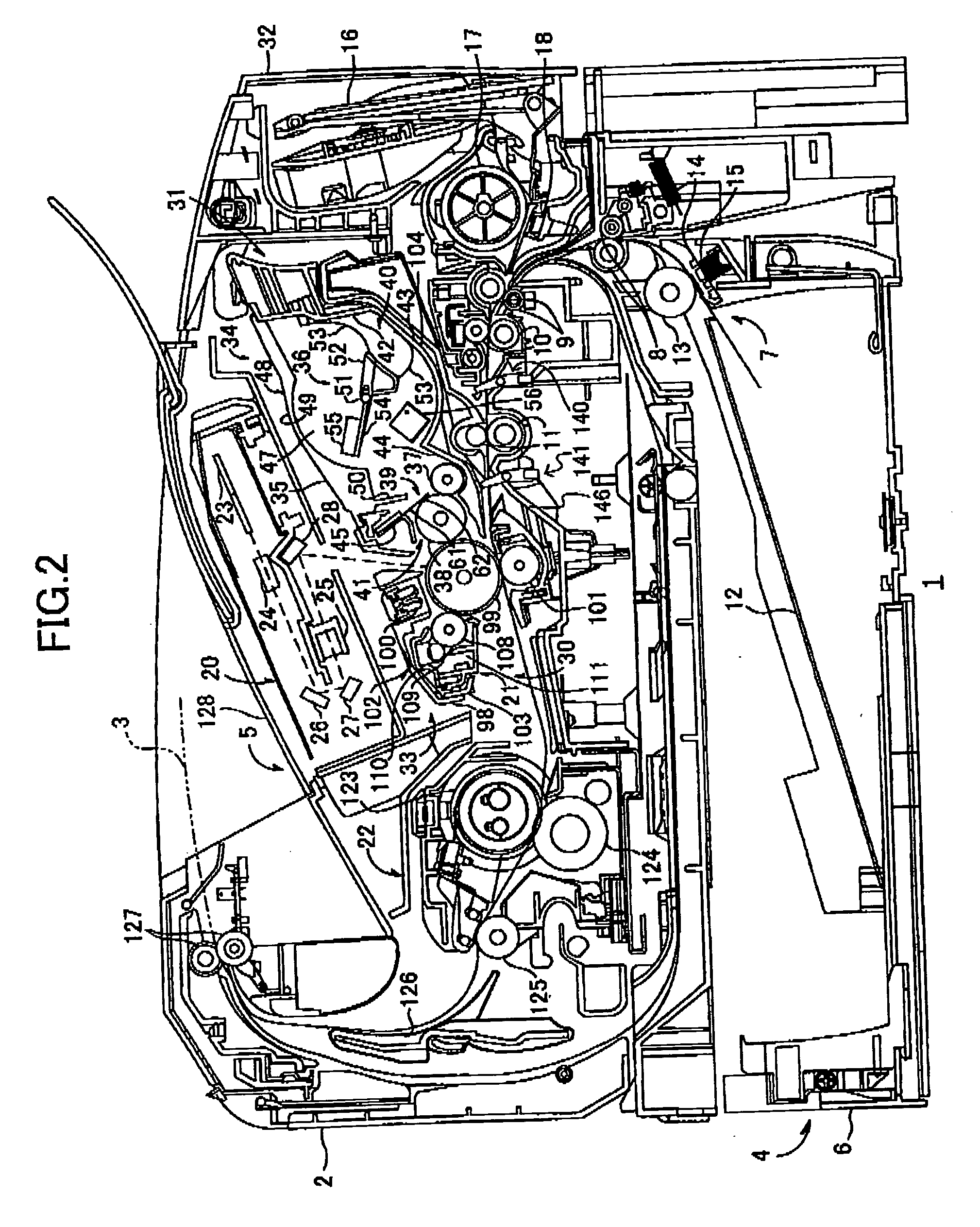
[0064] The paper tray 6 is detachably mounted in the lower section of the main frame 2 and functions to accommodate stacked sheets 3 of paper or another recording medium (see FIG. 2).

[0065] The discharge tray 128 functions to support discharged sheets 3 after the laser printer 1 has formed an image thereon.

[0066] The ventilating holes 132a and 132b facilitate the dissipation of heat from the inside of the main frame 2. The ventilating holes 132a and 132b are configured of numerous elongated holes.

[0067] A network interface 154 (see FIG. 13)...

second embodiment

[0274] In the laser printer 1 of the second embodiment, a sensor (not shown) is provided for detecting the open and closed status of the front cover 32 and for transmitting the detection results to the control unit 150.

[0275] The laser printer 1 of the second embodiment described above includes the sensing unit 140 that changes in detection status when one of the process cartridge 21 and inspection cartridge 180 is mounted in the laser printer 1; and the sensing unit 141 that changes in detection status when at least the other of the process cartridge 21 and the inspection cartridge 180 is mounted in the laser printer 1. The CPU 151 of the control unit 150 identifies the type of cartridge mounted in the laser printer 1 based on the detection results received from the sensing units 140 and 141.

[0276] Further, the sensing units 140 and 141 are provided on the conveying path of the sheet 3. Accordingly, the position of the sheet 3 can be detected based on the change in detection statu...


PUM


Abstract

A laser printer having a self-diagnostic function includes a first sensing unit that changes in detection status when one of a process cartridge and an inspection cartridge is mounted therein, and a second sensing unit that changes in detection status when at least the other of the process cartridge and inspection cartridge is mounted therein. A control unit of the laser printer identifies the type of cartridge mounted in the laser printer based on detection results from the first and second sensing units and switches the operating mode of the laser printer from a normal mode for performing image-forming operations to a self-diagnostic mode for diagnosing the status of its components when the control unit determines that the inspection cartridge is mounted in the laser printer.

Description

INCORPORATION BY REFERENCE [0001] The present application claims priority under 35 U.S.C. §119 to Japanese Patent Application No. 2004-233432 filed on Aug. 10, 2004. The content of the application is incorporated herein by reference in its entirety. BACKGROUND OF THE INVENTION [0002] 1. Field of the Invention [0003] The present invention relates to an image-forming device for forming images on a recording medium. [0004] 2. Description of the Related Art [0005] Image-forming devices having a function for detecting abnormalities and the like in the operating state of the device, such as that disclosed in Japanese Utility Model Application Publication No. HEI-6-87963, are well known in the art. With these image-forming devices, an external operation can be performed to switch the operating mode of the image-forming device between an image-forming mode for forming images on a recording medium and a self-diagnostic mode for performing a self-diagnosis of various components in the image-f...

Claims


Application Information

Patent Timeline
Patent Type & Authority Applications(United States)
IPC IPC(8): G03G15/00
CPCG03G15/50G03G21/1896G03G15/556G03G2221/1892G03G2215/00109
Inventor INUKAI, KATSUMI
Owner BROTHER KOGYO KK
Why Eureka
Try Eureka