Homogeneous charge compression ignition and barrel engines

a technology of compression ignition and charge, which is applied in the direction of combustion engines, internal combustion piston engines, machines/engines, etc., can solve the problems of slow response to changes in running conditions, significant variations in power output of different cylinders, and non-optimal approaches, and achieve the effect of rapid raising the compression level

Inactive Publication Date: 2006-02-23
THOMAS ENGINE CO LLC
View PDF23 Cites 56 Cited by
  • Summary
  • Abstract
  • Description
  • Claims
  • Application Information

AI Technical Summary

Benefits of technology

[0037] An alternative embodiment of a rapid compression method includes the steps of providing an internal combustion engine with a combustion chamber and introducing a mixture of air and fuel into the combustion chamber. The mixture is then compressed and combusted to create a pressurized gaseous combustion product. A portion of the pressurized gaseous combustion product is then captured and substantially all of the remainder of the gaseous combustion produce is exhausted from the combustion chamber. A fresh mixture of air and fuel is then introduced into the combustion chamber and compressed. The held portion of the pressurized gaseous combustion product is then released into the combustion chamber to rapidly raise the compression level.

Problems solved by technology

This is particularly true as engines age and combustion residue builds up in individual cylinders.
Either approach is non-optimal.
As with the case of modulating air-fuel ratios, large differences in intake temperature will cause significant variations in the power output of different cylinders.
The drawbacks with EGR are that responsiveness to changes in running conditions is typically slow due to the inertia of the gasses, although this problem could be addressed.
As with air-fuel and temperature modulation, large amounts of EGR can reduce power output.

Method used


Image

  • Homogeneous charge compression ignition and barrel engines
  • Homogeneous charge compression ignition and barrel engines
  • Homogeneous charge compression ignition and barrel engines

Examples


Embodiment Construction

HCCI Barrel Engine

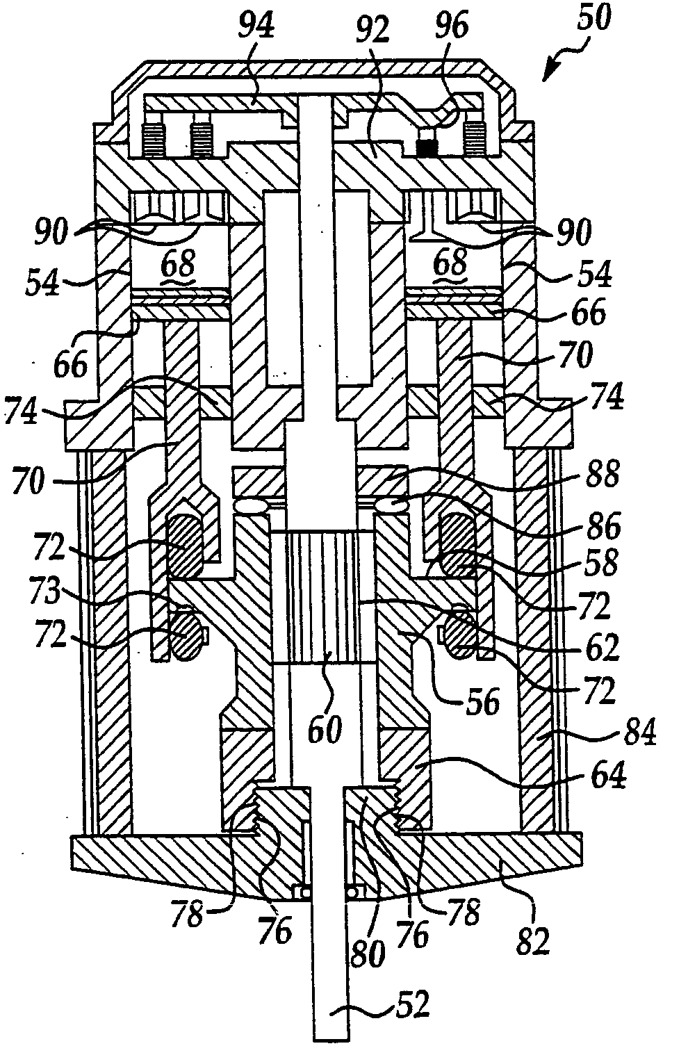
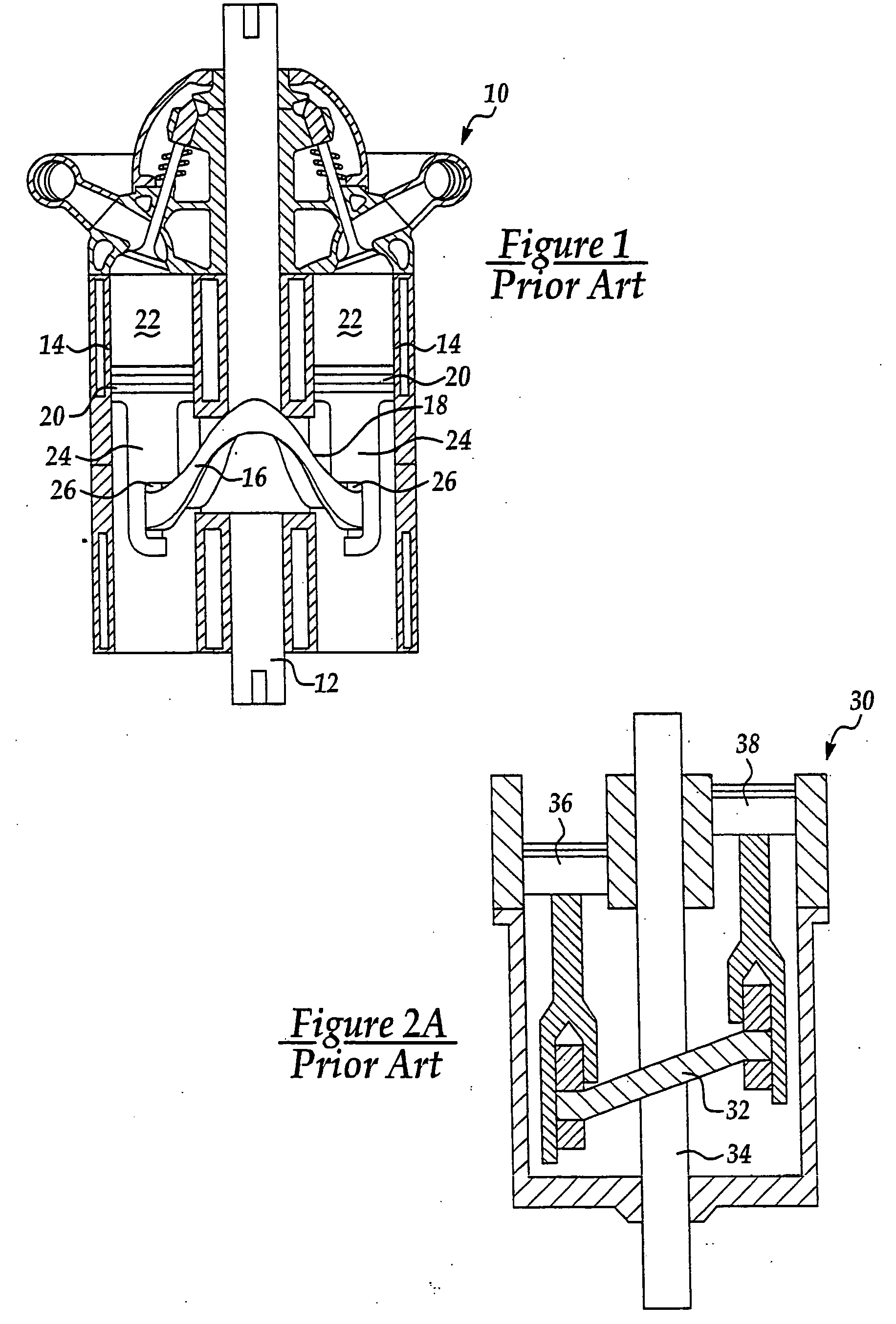
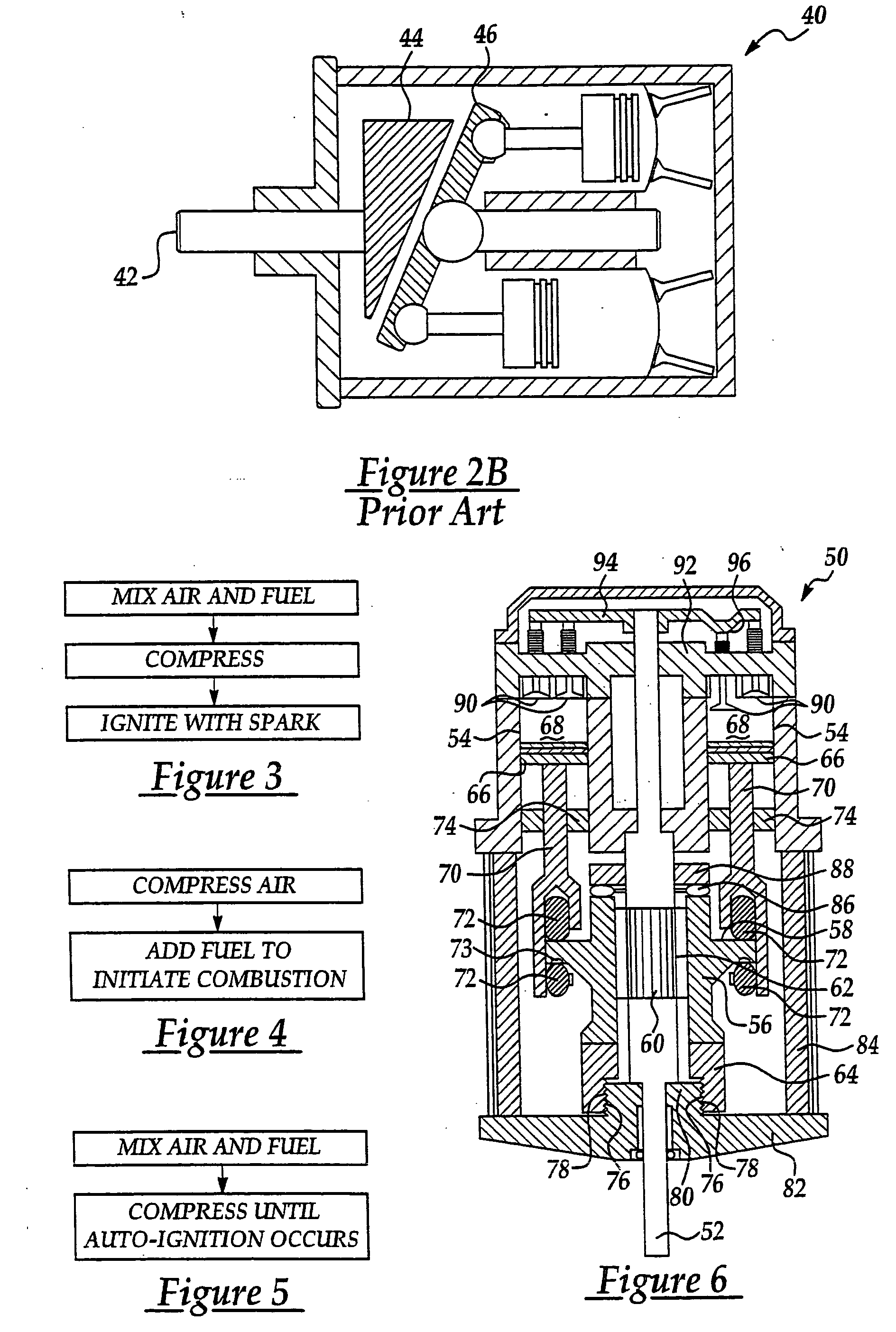
[0079] The present invention is directed to improvements in the class of internal combustion engines referred to herein as barrel engines and to improvements in homogenous charge compression ignition (HCCI) engines, either in combination or separately. In addition, various aspects of the present invention are applicable to engine configurations other than barrel engines and to compression strategies other than HCCI. As discussed in the Background of the Invention, a barrel engine is a type of internal combustion engine that does not include a traditional crankshaft to reciprocate pistons in cylinders. Instead, in a barrel engine, one or more pistons usually mechanically communicate with a track or plate that has a cam surface that undulates towards and away from the cylinders as the engine turns. The mechanical communication between the pistons and the cam surface causes the pistons to reciprocate in their cylinders as the track or plate rotates with respect to the...


PUM


Abstract

A homogenous charge compression ignition barrel engine includes an engine housing with a first and second end. An elongated power shaft is longitudinally disposed in the engine housing and defines a longitudinal axis of the engine. A plurality of cylinders surround the longitudinal axis with each cylinder having a closed end and an open end. Each cylinder has a central axis. The open ends of the cylinders are each generally directed toward the first end of the housing. An intake system is operable to introduce a combustible mixture of air and fuel into each of the cylinders. A track is disposed between the first end of the housing and the open ends of the cylinders such that a portion of the track is disposed generally in alignment with the central axis of each of the cylinders. The track has a cam surface that longitudinally undulates with respect to the open ends of the cylinders. A portion of the cam surface is disposed generally in alignment with the central axis of each of the cylinders. The track and the cylinders are rotatable with respect to each other such that the undulating cam surface moves with respect to the open ends of the cylinders. A piston is moveably disposed in each of the cylinders such that a combustion chamber is defined between the piston and the closed end of the cylinder. Each piston is in mechanical communication with the cam surface of the track such that as the cylinders and the track move with respect to each other, the pistons reciprocate within the cylinders. Each cylinder is operable to compress a combustible mixture until the mixture auto ignites, without the introduction of a spark.

Description

REFERENCE TO RELATED APPLICATIONS [0001] This application claims priority from U.S. provisional patent application Ser. Nos. 60 / 244,349, filed Oct. 30, 2000; 60 / 252,280, filed Nov. 21, 2000; 60 / 260,256, filed Jan. 8, 2001; 60 / 261,060, filed Jan. 11, 2001; and 60 / 267,958, filed Feb. 9, 2001; and is a continuation-in-part of U.S. patent application Ser. No. 09 / 937,543, filed Sep. 26, 2001, which is a U.S. National Phase of PCT / US00 / 07743, filed Mar. 22, 2000, which claims priority from U.S. provisional patent application Ser. Nos. 60 / 125,798, filed Mar. 23, 1999; 60 / 134,457, filed May 17, 1999; 60 / 141,166, filed Jun. 25, 1999, and 60 / 147,584, filed Aug. 6, 1999, the entire contents of all of which are incorporated herein by reference.FIELD OF THE INVENTION [0002] The present invention relates generally to internal combustion engines and, more particularly, to homogenous charge compression ignition engines and barrel engines. BACKGROUND OF THE INVENTION [0003] Internal Combustion Engin...

Claims


Application Information

Patent Timeline
Patent Type & Authority Applications(United States)
IPC IPC(8): F02B75/18
CPCF02B19/12F02B19/165Y02T10/125F02B75/26F02B19/18Y02T10/12
Inventor THOMAS, CHARLES RUSSELL
Owner THOMAS ENGINE CO LLC
Why Eureka
Try Eureka