
Wire spool guide assembly

Inactive Publication Date: 2006-02-23
GIOVANNONI JAMES
View PDF26 Cites 32 Cited by
  • Summary
  • Abstract
  • Description
  • Claims
  • Application Information

AI Technical Summary

Benefits of technology

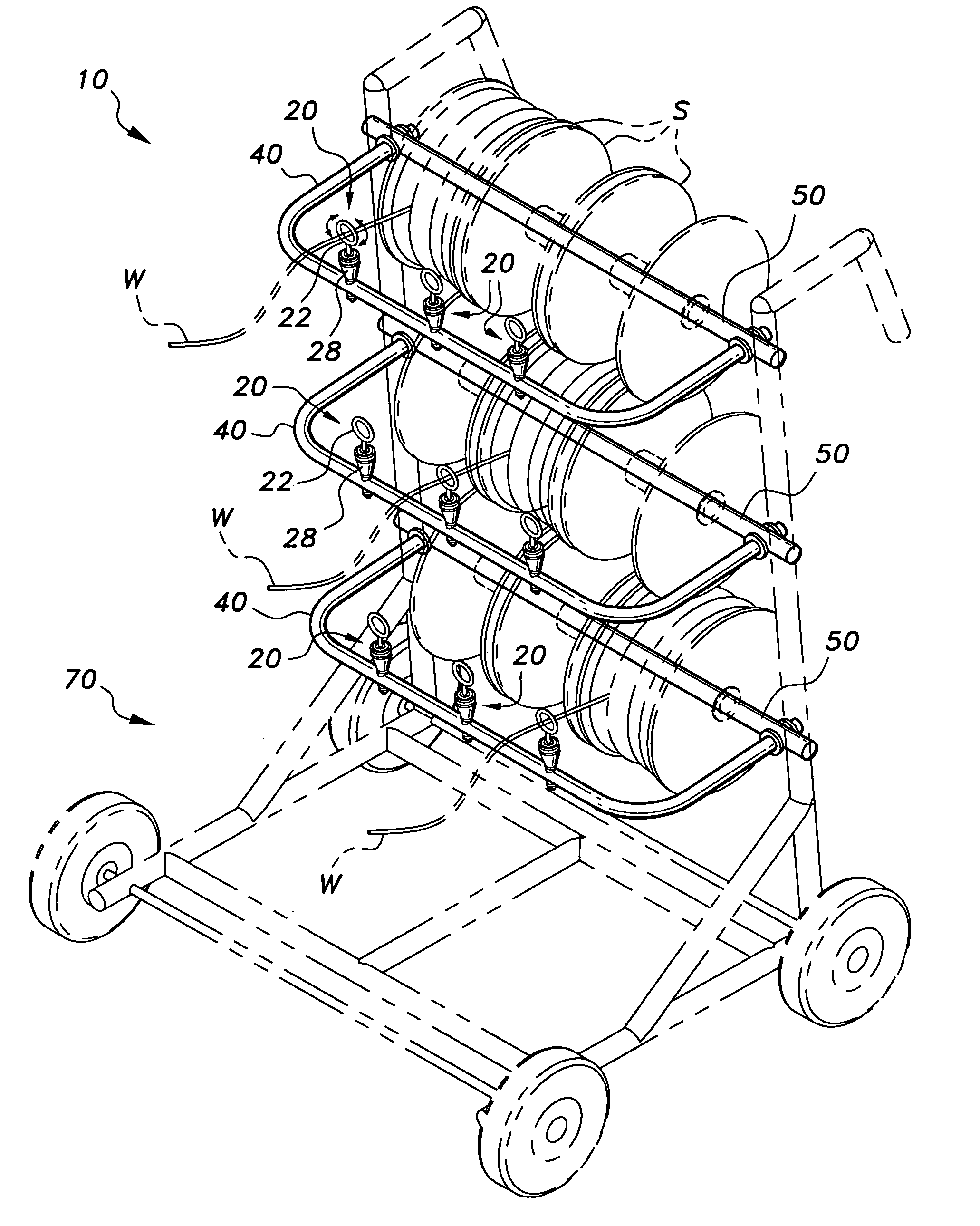
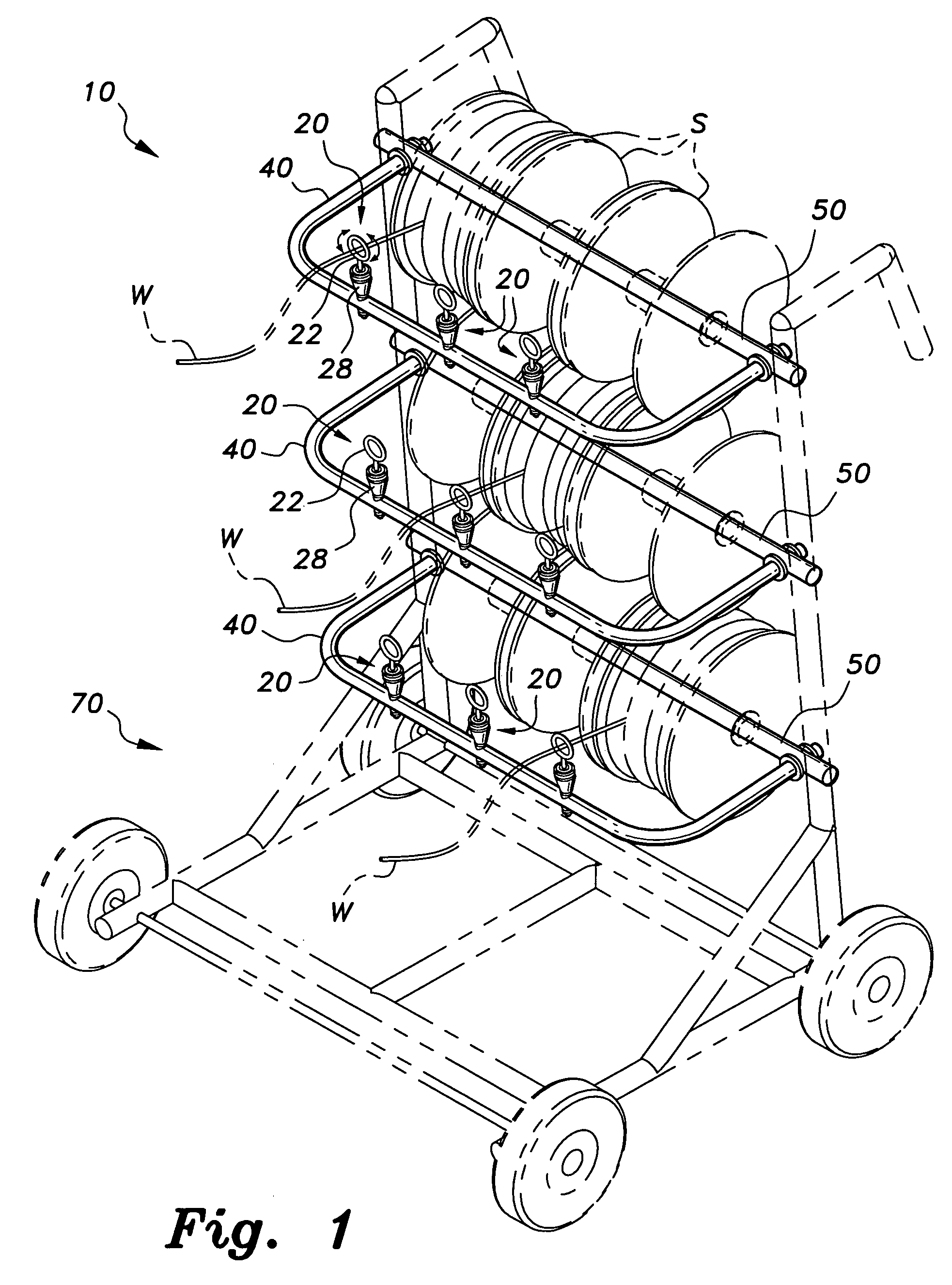
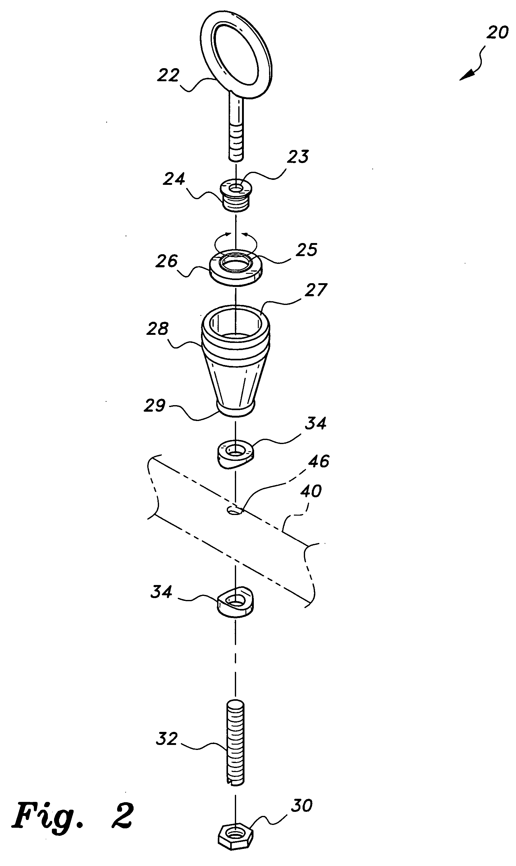
[0026] The handle bar serves to mount the wire spool guide(s) The guides are positioned on the handle bar to be directly in front of each spool on the spindle. The guide has an eyebolt, a ball bearing, and a support frame. The eyebolt is rotatably mounted to the support frame via the ball bearing, allowing the eyebolt to rotate about a vertical axis. Wire is threaded through the eyebolt to serves as the conduit through which wire is dispensed. Friction is created as wire is pulled through the eyebolt that slows the speed at which the spool rotates on the spindle. The guide nevertheless acquiesces to the direction of a user's pull by the eyebolt being able to rotate about the ball bearing. The frame of the guide, however, is fixed on the handle bar by a fastener disposed at a bottom end of the guide.

Problems solved by technology

Wire management is a common problem for electricians especially when wiring houses and buildings.
However, the spindle does not prevent wires from becoming tangled.

Method used


Image

  • Wire spool guide assembly
  • Wire spool guide assembly
  • Wire spool guide assembly

Examples


Embodiment Construction

[0031] A wire spool guide assembly is designated as 10 in the figures. The wire spool guide assembly 10 is a conduit through which wire may be dispensed in a controlled and orderly manner. As shown in FIG. 1, the assembly 10 includes a wire spool cart 70 having at least one spindle 50 on which spools S of wire W are disposed. The cart 70 may be any commercially sold wire spool cart used to retain spools S for wiring jobs. The spindle 50 holds the spools S of wire and serves as a mounting point for a handle bar 40.

[0032]FIG. 3 shows the handle bar 40 structure. At each end of the spindle 50 are holes 52 through which ends of the handle bar 40 are inserted. Once the ends of the handle bar 40 are inserted through the holes 52, setscrew collars 42 are used to secure the handle bar 40 to the spindle 50. The setscrew collars 42 are, preferably, one-piece shaft collars that use at least one set screw 44 to tighten the collar 42 to the handle bar 40. However other types of collars or clamp...


PUM


Abstract

The wire spool guide assembly is a conduit through which wire is dispensed in a controlled and orderly manner. The assembly has at least one wire spool guide, a handle bar and a spindle. The spindle may be a single spindle or part of a wire spool cart. The spindle is used to hold wire spools and the handle bar. The handle bar serves to hold the guide. The guide includes an eyebolt rotatably mounted to a support frame via a ball bearing. The eyebolt guides wire as it is dispensed from the spool acquiescing to the direction of the user's pull. Friction, created as wire is pulled through the eyebolt, slows the speed at which the spool rotates on the spindle. The frame of the guide, however, is fixed on the handle bar by a fastener disposed at a bottom end of the guide.

Description

BACKGROUND OF THE INVENTION [0001] 1. Field of the Invention [0002] The present invention relates to wire guides, and more particularly to a rotatable wire guide, for use with a spool of wire, that adjusts to the direction in which wire is pulled from a spool. [0003] 2. Description of the Related Art [0004] Wire management is a common problem for electricians especially when wiring houses and buildings. Normally more than one person is needed on a wiring job to help keep spooled wire from entangling. Spools of wire are tethered to a spindle or rod to prevent the spools from becoming mobile as the wire is pulled off the spool. However, the spindle does not prevent wires from becoming tangled. A device is desired that will allow wire to be dispensed in any direction and in an orderly manner without becoming entangled. [0005] U.S. Pat. No. 986,020, issued to Mills on Mar. 7, 1911, describes a wire feeder. The feeder has an arm that rotates between two cones of wire to dispense wire thr...

Claims


Application Information

Patent Timeline
IPC IPC(8): B65H49/20B65H57/06
CPCB65H57/06B65H49/321B62B2202/025
Inventor GIOVANNONI, JAMES
Owner GIOVANNONI JAMES
Learn More