Synchronous transmission network system

a network system and synchronous transmission technology, applied in the field of synchronous transmission network systems, can solve the problems of deteriorating clock accuracy, loss of information that is called a slip, and inability to synchronize the whole network with the clock supplied from one single master station in these master stations

Inactive Publication Date: 2006-02-23
FUJITSU LTD
View PDF10 Cites 33 Cited by
  • Summary
  • Abstract
  • Description
  • Claims
  • Application Information

AI Technical Summary

Benefits of technology

[0026] According to the present invention, each of the nodes configuring the synchronous transmission network system can automatically determine the master station for supplying the optimum clock.

Problems solved by technology

The reason why so is that if the synchronization can not be established due to deterioration of the clock accuracy, there occurs a loss of information that is called a slip.
As a matter of fact, however, in the process of distributing a clock to respective nodes (slave stations) from a node (master station) serving as a clock supply source, the clock accuracy gradually gets deteriorated as it is affected by a phenomenon called a wander occurred depending on a distance and a degree of refraction of an optical fiber cable for connecting between the nodes and on fluctuations in weather (temperature) and by a great variety of processes (a photoelectric signal conversion, and termination and generation of an SOH (Section OverHead)), etc. executed in the station.
In a network where a plurality of master stations exist, however, the whole network can not be synchronized with the clock supplied from one single master station in these master stations.

Method used


Image

  • Synchronous transmission network system
  • Synchronous transmission network system
  • Synchronous transmission network system

Examples


embodiment

Operational Effect of Embodiment

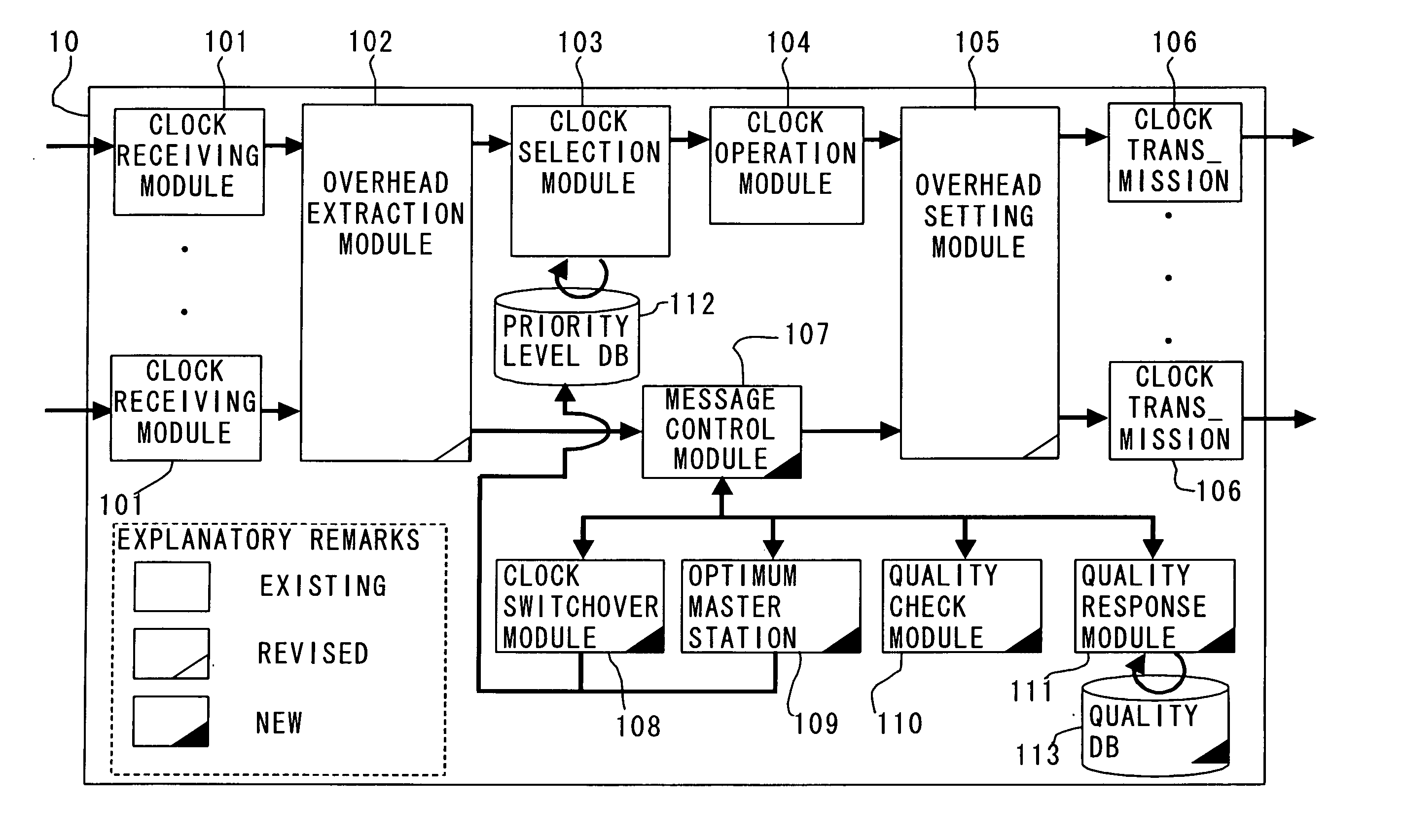
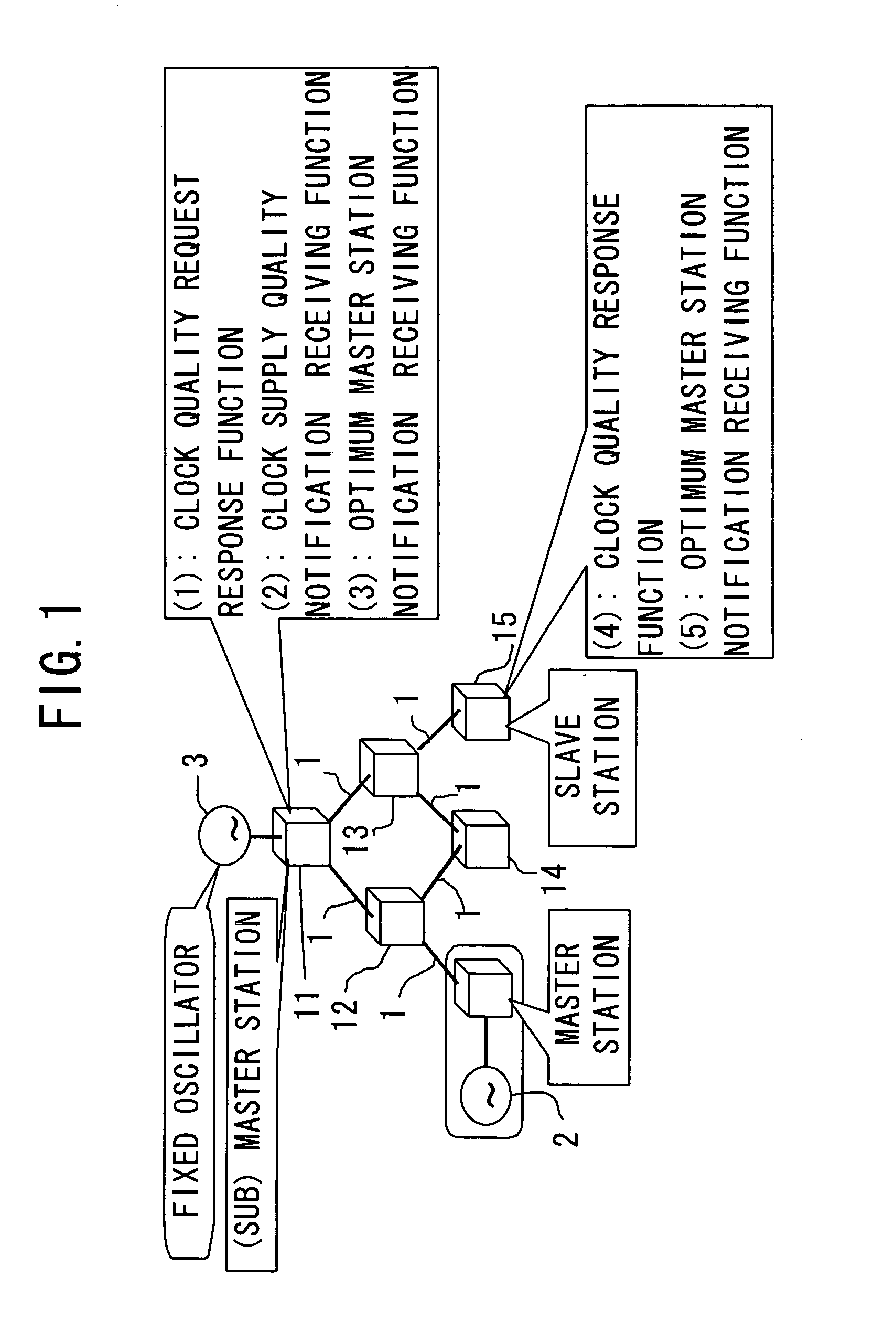
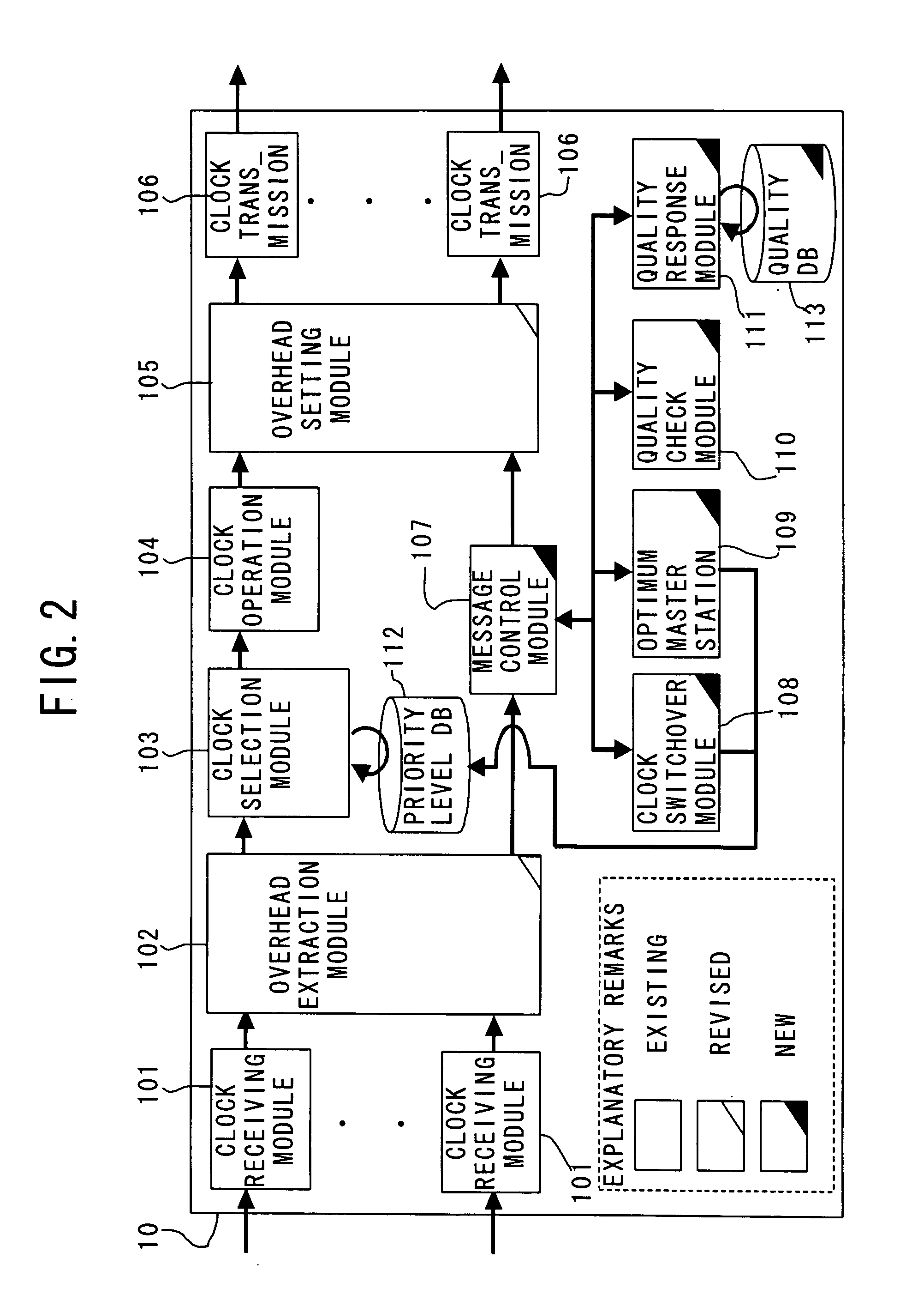
[0176] In the system according to the embodiment, when the system constitution is changed, in the post-change system constitution, the optimum master station capable of supplying the optimum clock is determined, and the setting is automatically changed so that each node preferentially selects the clock supplied by this optimum master station.

[0177] For determining this type of optimum master station, the master station and the sub-master station having the clock sources send the [quality requests] (e.g., the [quality requests]41, 42 sent by the sub-master station A) to the other nodes.

[0178] Each of the nodes having received the [quality requests] calculates the clock quality of the self-node from the information stored on the quality DB 113 and the information such as the accumulated clock quality, etc. set in the [quality request]. Then, the [quality response (e.g., the [quality response]51 sent by the node E) in which this clock quality is set, i...


PUM


Abstract

A synchronous transmission network system has a plurality of nodes including a plurality of clock supply nodes and all the nodes synchronize with a clock supplied from one of clock supply nodes as a master, wherein each clock supply node includes a transmission module for transmitting a quality request message toward all other nodes, a receiving module for receiving quality response messages from all the other nodes, a quality determination module for determining clock supply quality information, a notifying module for notifying other clock supply node serving as the master of the clock supply quality information, and a node determination module for determining an optimum clock supply node exhibiting the best clock supply quality on the basis of the notified clock supply quality information and the clock supply quality information of the self-node.

Description

BACKGROUND OF THE INVENTION [0001] 1. Field of the Invention [0002] The present invention relates to a synchronous transmission network system. [0003] 2. Description of the Related Art [0004] In a network synchronous digital transmission method typified by an SDH (Synchronous Digital Hierarchy) and a SONET (Synchronous Optical Network), it is required that a whole network is operated by one single clock source. For attaining this, clock signals exhibiting uniform high accuracy need spreading over the whole network. The reason why so is that if the synchronization can not be established due to deterioration of the clock accuracy, there occurs a loss of information that is called a slip. [0005] As a matter of fact, however, in the process of distributing a clock to respective nodes (slave stations) from a node (master station) serving as a clock supply source, the clock accuracy gradually gets deteriorated as it is affected by a phenomenon called a wander occurred depending on a dista...

Claims


Application Information

Patent Timeline
Patent Type & Authority Applications(United States)
IPC IPC(8): H04J3/06
CPCH04J3/0641H04J3/14H04J3/0679H04J3/0647
Inventor NAKAMURA, KAZUHIKOKOGA, MASAYUKIONO, JUNJIHAMACHI, HIROKI
Owner FUJITSU LTD
Why Eureka
Try Eureka