
Apparatus and method for reusable, no-waste collapsible tube dispensers

a dispenser and reusable technology, applied in the field of screw and cap mechanism, can solve the problems of limited tube capacity, inability to support the complete, controlled dispensing of contents, and inability to re-use the technology of collapsible tubes,

Inactive Publication Date: 2006-03-02
SCOTT ANDERSON & SUSAN POTTISH +2
View PDF38 Cites 6 Cited by
  • Summary
  • Abstract
  • Description
  • Claims
  • Application Information

AI Technical Summary

Problems solved by technology

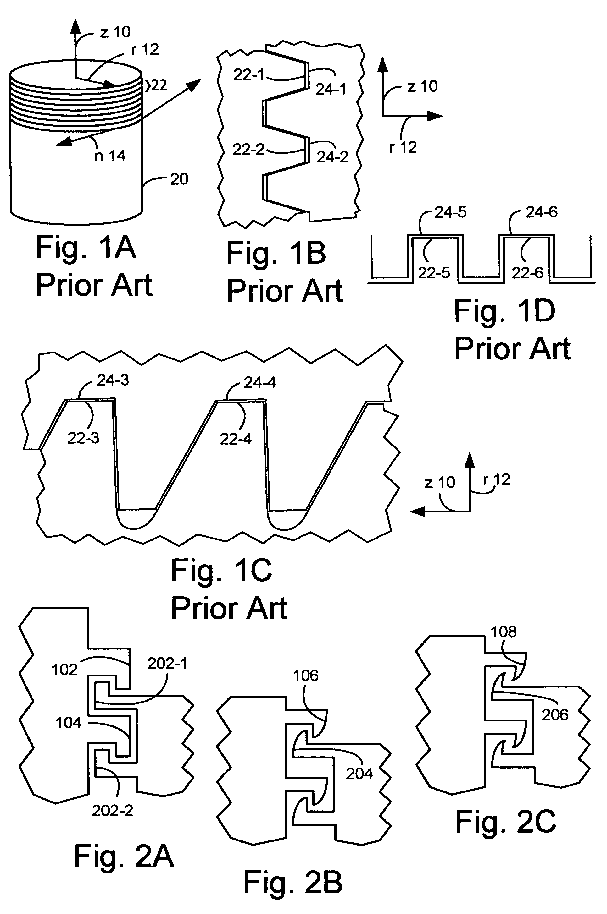
There are problems with the collapsible tube technologies of the prior art.
They do not lend themselves both to being reusable and supporting the complete, controlled dispensing of their contents.
This tube may be limited to applications in which there is no unexpected or forceful pressure applied to the tube.
The tube may also be limited to applications in which a high degree of barrier to the environment is not critical, such as pharmaceuticals, because the opening does not clean itself when closing except to the degree that it draws contents outside the tube to the inside of the tube.
It may be undesirable for personal care products or other products demanding a high degree of aesthetic features, such as oversized caps allowing the tube to stand vertically.
These one-time use containers are not reusable, and represent a significant amount of overhead both for the manufacturer and for the ecology of people and systems, which must cope with these discarded containers.
None on the market, however, are both reusable and completely collapsible.
Thus, they do not dispense all their contents.

Method used


Image

  • Apparatus and method for reusable, no-waste collapsible tube dispensers
  • Apparatus and method for reusable, no-waste collapsible tube dispensers
  • Apparatus and method for reusable, no-waste collapsible tube dispensers

Examples


Embodiment Construction

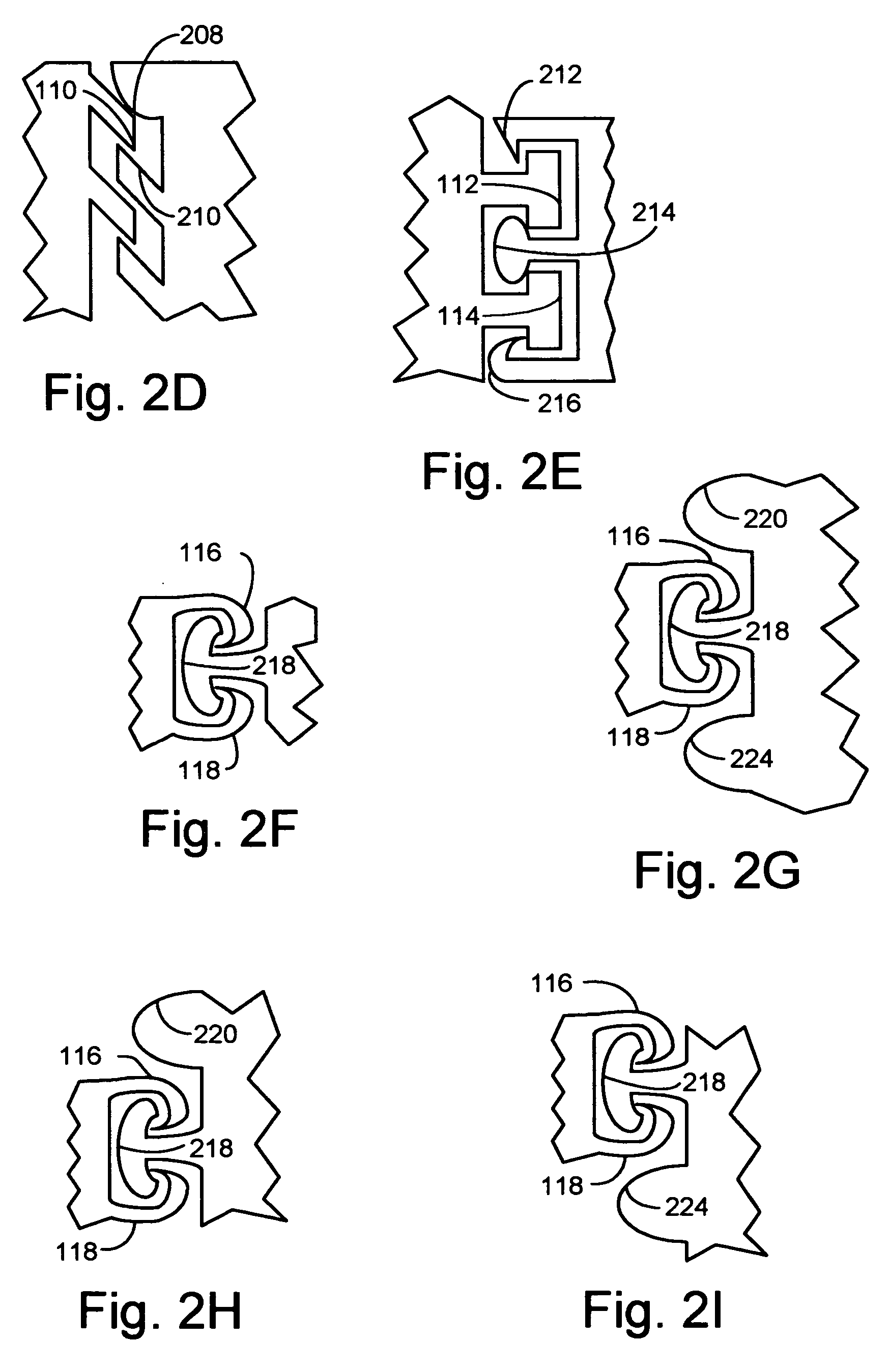
[0050]FIGS. 2A to 2I show various matching ridged screw thread forms in the normal cross-section. In certain embodiments, the ridged thread form on the left side, known hereafter as the left ridged thread form, may be preferred as the internal thread form. The ridged thread form on the right side, known hereafter as the right ridged thread form, would be the external thread form. Alternatively, the right ridged thread form may be preferred as the internal thread form and the left ridged thread form would be the external thread form. A ridged thread will refer to a thread that has its terminating end(s) bulge and / or bend.

[0051] In FIGS. 2D to 2I, the ridged thread form on either the left side or right side may not be immediately repeated. The thread pattern of the left ridged thread form is not immediately repeated in the thread pattern of the right ridged thread form. In FIGS. 2E, 2G, 2H and 2I, the right ridged thread form varies in each successive ridged thread.

[0052] In FIG. 2A...


PUM


Abstract

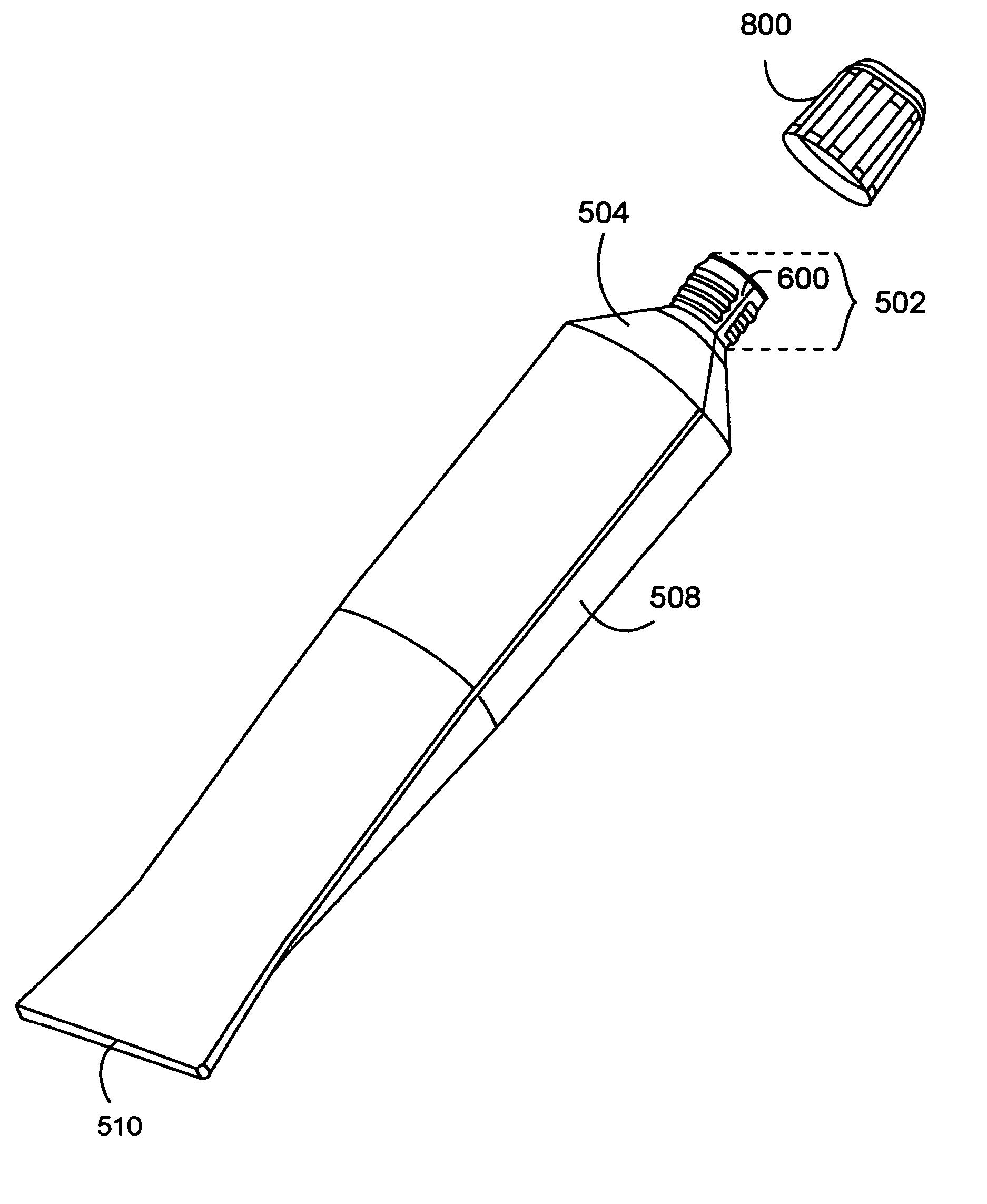
The invention includes a method of using a cap containing an internal thread form matching an external thread form on a flexible throat for a collapsible tube enclosing at least one contained product. Twisting the cap engages the internal thread form and the external thread form. These collectively urge the cap and the flexible throat to seal the contained product into the collapsible tube. Deforming the flexible throat through squeezing the collapsible tube dispenses essentially all the product. The collapsible tube may preferably include an external thread form on a flexible throat coupled to a flexible shoulder. The external thread form mates to a cap with an internal thread form urging the flexible throat to seal against the cap when the cap is twisted onto the flexible throat. The flexible throat and flexible shoulder flatten to dispense essentially all of the product.

Description

BACKGROUND OF THE INVENTION [0001] 1. Field of the Invention [0002] The invention relates to screw and cap mechanisms with particular application to forming collapsible tube dispensers. [0003] 2. Background Information [0004] The earliest collapsible tube dispensers in the US patent database date from the early nineteenth century. Since that time, there has been continued innovation, leading to the various collapsible tube dispensers used for pharmaceuticals, personal care products, toothpaste, foods, artist's paints, glues, hazardous chemicals, grease products and viscous plastics, to name some of the more common uses of these tubes. As used herein, personal care products include, but are not limited to, cosmetics, facial care products, skin care products, and / or hair care products. [0005] There are problems with the collapsible tube technologies of the prior art. They do not lend themselves both to being reusable and supporting the complete, controlled dispensing of their contents...

Claims


Application Information

Patent Timeline
IPC IPC(8): B65D35/00B65D37/00
CPCB65D35/08B65D35/44B65D41/04B65D2231/00Y02W30/80
Inventor POTTISH, SUSANMULLIN, HOWARDANDERSON, SCOTTPOTTISH, MORRIS
Owner SCOTT ANDERSON & SUSAN POTTISH
Learn More