Digital imaging assembly & methods thereof

a digital imaging and assembly technology, applied in the field of coherent radiation imaging systems, can solve the problems that foreign contrast agents often harm biological samples, and achieve the effect of effectively eliminating speck nois

Inactive Publication Date: 2006-03-02
TECH INNOVATIONS LLC +1
View PDF6 Cites 10 Cited by
  • Summary
  • Abstract
  • Description
  • Claims
  • Application Information

AI Technical Summary

Benefits of technology

[0024] The method of embodiments of the present invention involves a process of controlled statistical processing, where speckle noise can be effectively eliminated while preserving object phase. In summary, a process is employed where dynamic phase information is encoded onto the illuminating coherent beam, and measured, before input coherence is lost. Given the current availability of very stable and long coherence length lasers (with line widths on the order of 1 kHz), high-speed imaging, and high-speed phase processing; the realization of phase-controlled statistics is possible using embodiments of the present invention.
[0027] In another embodiment, the present invention allows one to achieve phase contrast edge enhancement. In one aspect of this embodiment, one utilizes object slices of a biological structure that are mostly suspended in an aqueous environment. In this aspect, light tends to go through (in transmission), occasionally being scattered and diffracted, with little absorption. This essentially describes a phase object. This is one of the reasons fluorescent dye markers are so popular with these objects in that they absorb a lot of light and, thus, render them easier to see. Phase contrast, on the other hand, uses small shifts in relative optical phase (which is on the order of a fraction of a wavelength) to see features of the object. This results in a much more sensitive and less imposing way to see things compared to absorptive imaging, which requires a foreign contrast agent to be applied; the foreign contrast agent often does harm to the biological sample.
[0029] In another embodiment, the present invention allows one to achieve high-speed imaging for observing biological processes in real time; thus, e.g., one may observe cellular, dynamic processes, in digital form, to enable automated analytics.
[0031] This microscope utilizes the phase of the light which is determined opto-electronically, in discreet coherent steps. After a coherent step, the optical statistics are changed in a highly controlled and pre-determined fashion and the phase is determined again. This is done repeatedly until one has attained enough information to remove speckle. By controlling the optical statistics in time, one can build up a quality image without the limitations of other optical microscopes.

Problems solved by technology

This results in a much more sensitive and less imposing way to see things compared to absorptive imaging, which requires a foreign contrast agent to be applied; the foreign contrast agent often does harm to the biological sample.

Method used


Image

  • Digital imaging assembly & methods thereof
  • Digital imaging assembly & methods thereof
  • Digital imaging assembly & methods thereof

Examples


Embodiment Construction

[0057] The present invention will now be described with reference to exemplary embodiments to which it is not limited. Variations and modifications will occur to skilled artisans which are encompassed within the present invention as defined in the claims appended hereto.

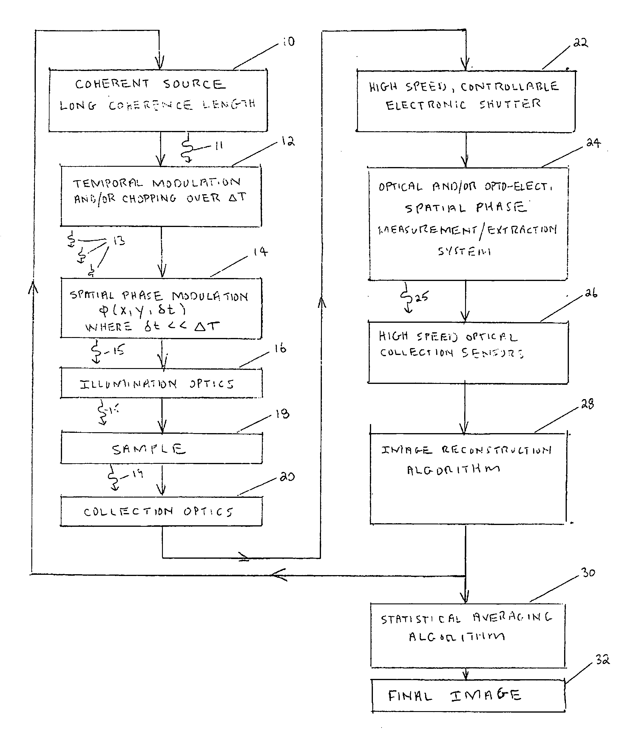
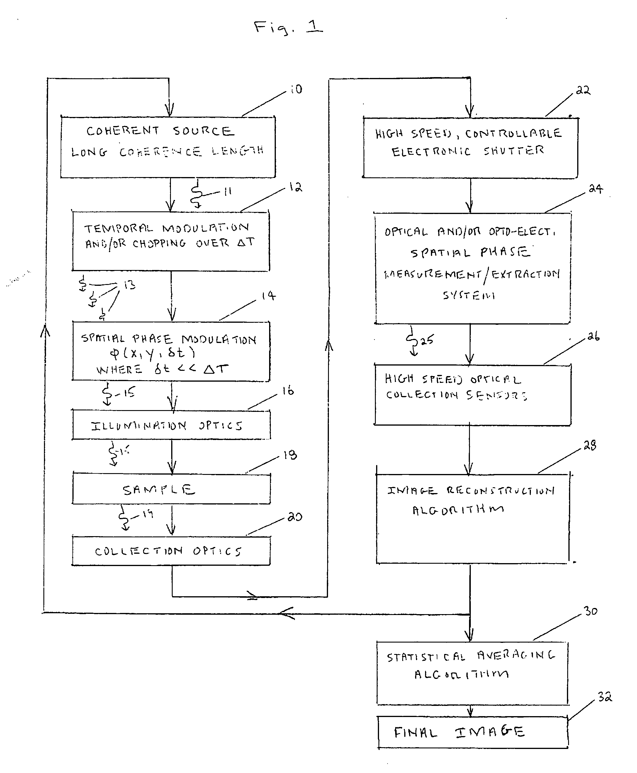
[0058]FIG. 1 is a block diagram illustrating an exemplary method in accordance with the present invention. A source of coherent radiation 10 provides the coherent wave 11 of radiation to be used to image the sample 18. As used in this specification, the term “coherent radiation” means electromagnetic radiation of the same, or almost the same, wavelength, and with definite phase relationships between different points in the field. See, e.g., page 423 of the “McGraw-Hill Dictionary of Scientific and Technical Terms,” Sixth Edition (New York, N.Y., 2003). Reference may also be had, e.g., to U.S. Pat. Nos. 6,272,095, 6,094,300, 6,055,044, 6,002,499, 5,963,626, 5,754,511, and the like. The entire disclosure of each of th...


PUM


Abstract

A coherent radiation imaging system that produces digital images with a reduced amount of speckle. Radiation from a long coherence length source is used to form an image of a sample. The output coherent wave is temporally divided into a plurality of wavelets. The spatial phase of each wavelet is then modulated a known and different amount. Each phase modulated wavelet illuminates the sample and is perturbed by its interaction with the sample. A spatial phase map of each perturbed wavelet is then created and converted to a sample image with an image reconstruction program. The plurality of sample images thus formed is statistically averaged to form a final averaged image. The high frequency speckle that is not optically resolvable tends to average to zero with continual statistical averaging, leaving only the optically resolvable lower frequency phase information.

Description

[0001] This application is a continuation-in-part of U.S. Non-Provisional application Ser. No. 10 / 983,053 filed Nov. 5, 2004, and claims the benefit of U.S. Provisional Application No. 60 / 518,918 filed Nov. 10, 2003, both herein incorporated by reference.FIELD OF THE INVENTION [0002] This invention relates in general to imaging systems, and more particularly to a coherent radiation imaging system that produces digital images with a reduced amount of speckle. BACKGROUND OF THE INVENTION [0003] In the field of imaging science, microscope designs have stayed fairly constant over time. A modern optical microscope has the same basic parts microscopes have had since their initial creation. A typical optical microscope includes the basic parts of a light source, a high power optical objective, a microscope body, and an eyepiece. The eyepiece is now commonly replaced with a focusing lens and photographic camera, or an electronic camera with an electronic area sensor. The electronic camera h...

Claims


Application Information

Patent Timeline
Patent Type & Authority Applications(United States)
IPC IPC(8): G01J5/02
CPCG02B27/48
Inventor PRELEWITZ, DAVID F.GRAY, ROBERT W.GERCHBERG, ROLFWEINER, MICHAEL L.
Owner TECH INNOVATIONS LLC
Why Eureka
Try Eureka