Sanitary sealed connector for fluid handling systems and storage devices

a technology of fluid handling system and connector, applied in the direction of fluid pressure sealing joints, flanged joints, sleeves/socket joints, etc., can solve the problems of missing devices designed to address, cost and weight of machined metal components,

Active Publication Date: 2006-03-02
MI
View PDF12 Cites 5 Cited by
  • Summary
  • Abstract
  • Description
  • Claims
  • Application Information

AI Technical Summary

Benefits of technology

[0009] In a fourth aspect of the claimed invention, a first sealing component radially extends from a first member end of a first tubular member. An annular groove is formed into a first end face of the first sealing component. A second sealing component of the sanitary fitting has a resilient rib integrally formed with the second end face and the second sealing component is incorporated into a cover that to prevent fluid communication from the first tubular member through the first member end. A clamp band secures the first and second sealing components together. Alternatively, the first sealing component is incorporated into a cover that prevents fluid communication from the second tubular member through the second member end. This embodiment is beneficial for fluid storage devices.

Problems solved by technology

While this four-part design has continued to be used to provide a sealed connection between adjoining pipes and to seal storage devices, the machined metal components add both cost and weight to the fluid handling device or storage container.
Despite this need, there exists an absence of devices designed to address the above noted desired improvements.

Method used


Image

  • Sanitary sealed connector for fluid handling systems and storage devices
  • Sanitary sealed connector for fluid handling systems and storage devices
  • Sanitary sealed connector for fluid handling systems and storage devices

Examples


Embodiment Construction

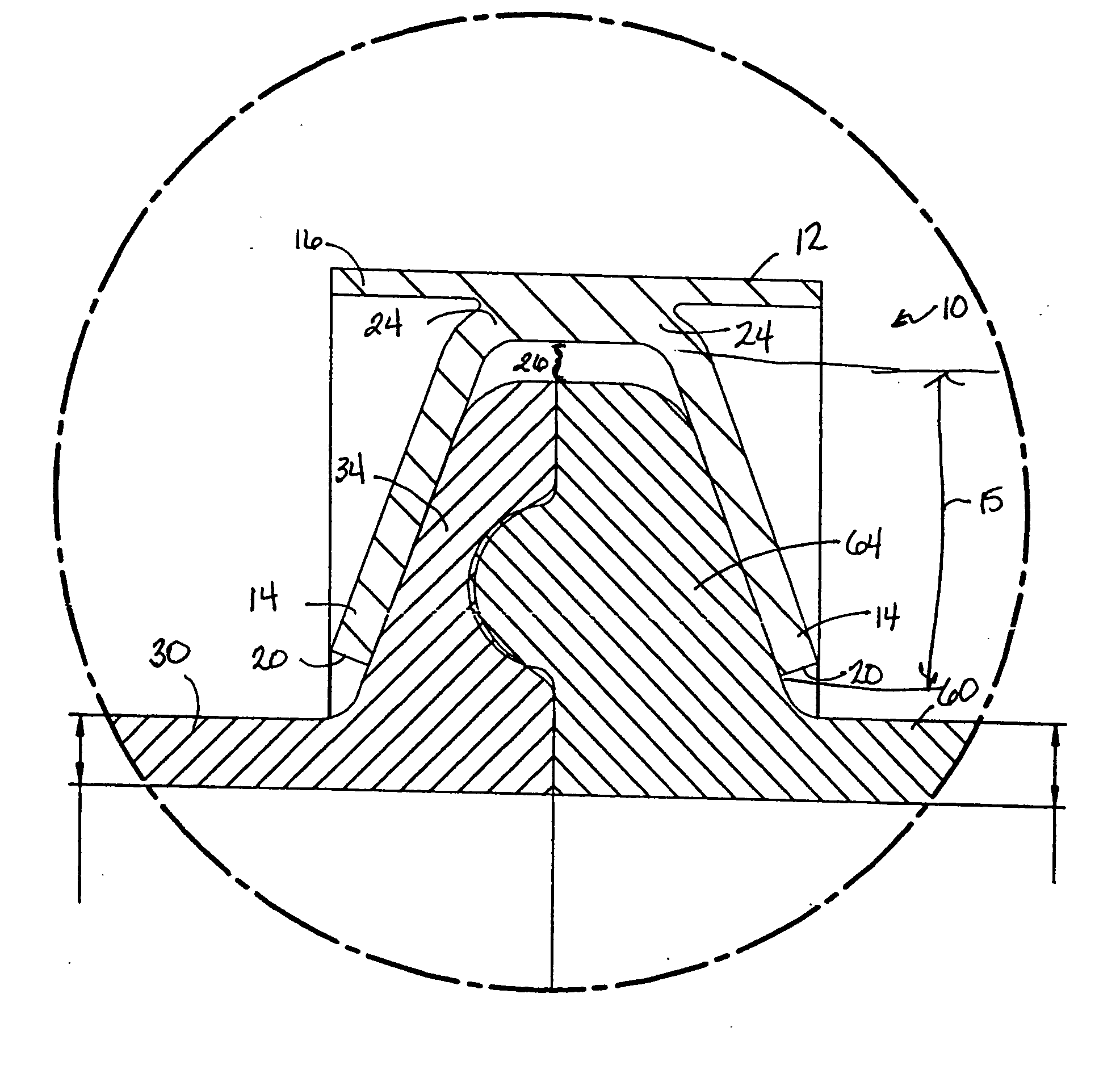
[0029] Referring to FIG. 1, a first embodiment of a sanitary connector 10 is depicted. The basic components of the sanitary connector 10 include a first tubular member 30, a second tubular member 60, and a clamp band 12.

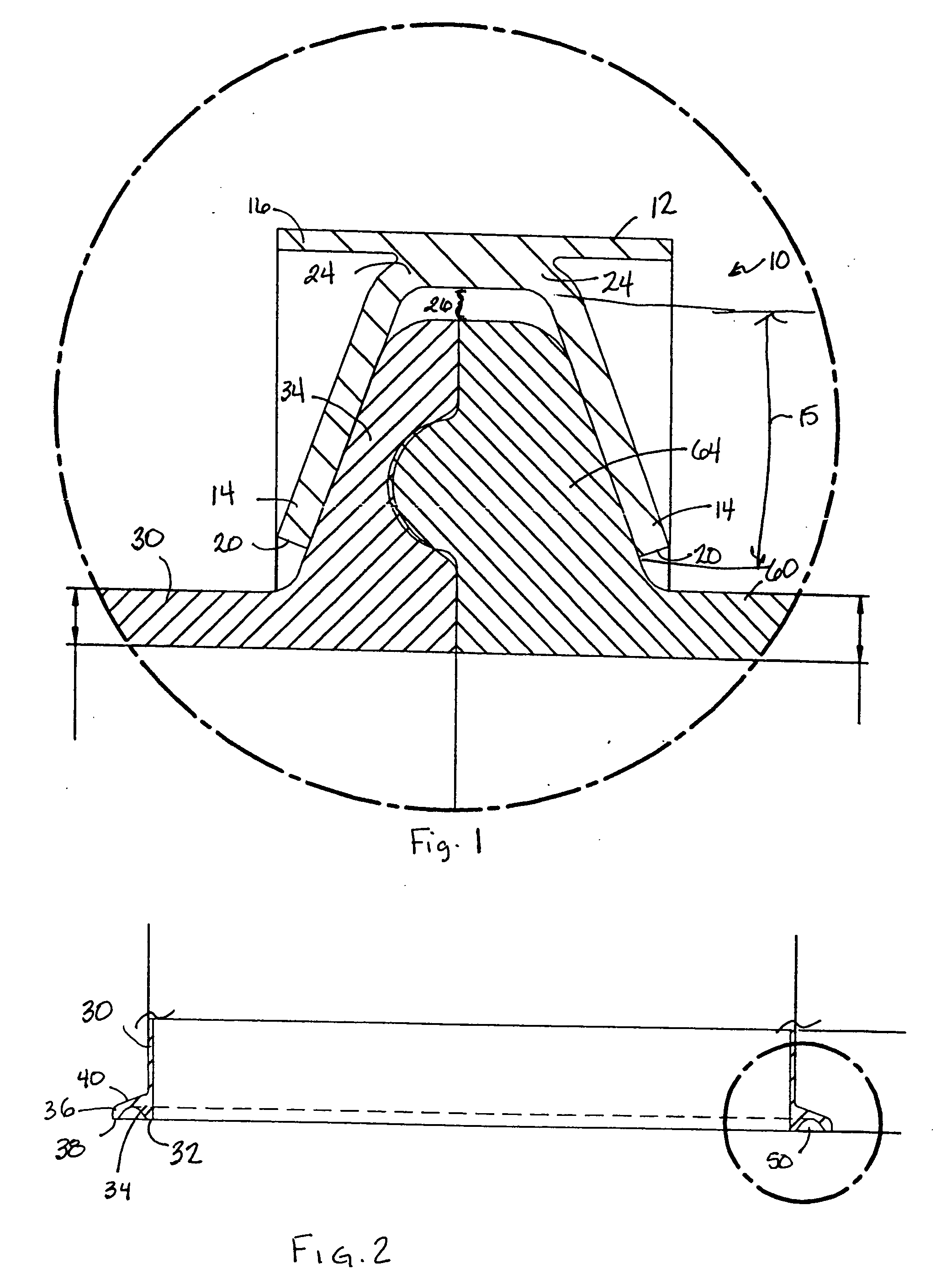
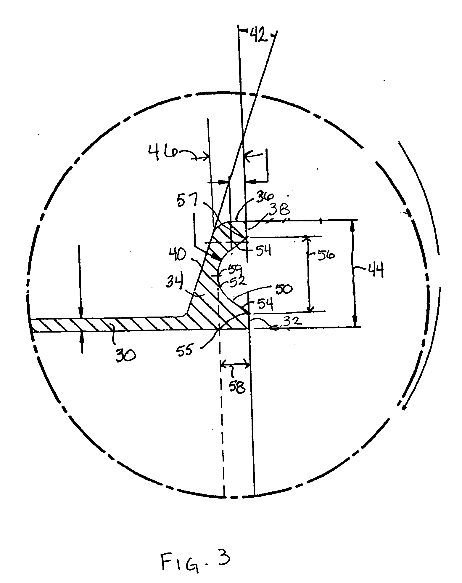
[0030] As may be seen in FIGS. 2 and 3, the first tubular member 30 has a first member end 32 from which a first sealing component 34 radially extends outward to a first component outer surface 36, encircling the first member end 32. The first sealing component 34 has a first end face 38 that is substantially flush with the first member end 32 and has a first end face width 44 (shown in FIG. 3). A first component back surface 40 extends between the first tubular member 30 and the first component outer surface 36, forming a first component angle 42 (shown in FIG. 3) with first end face 38.

[0031] Referring to FIG. 3, the first sealing component 34 includes an annular groove 50 formed into the first end face 38. Annular groove 50 is defined by a groove bottom portion ...


PUM


Abstract

A sanitary connector apparatus includes first and second tubular members coaxially aligned such that a first member end of the first tubular member is positioned toward a second member end of the second tubular member. First and second sealing components radially extend from the first and second member ends, respectively. An annular groove is formed into the first end face of the first sealing component and a corresponding resilient rib is integrally formed with the second end face of the second sealing component. A clamp band, secured around the outer perimeter of the first and second sealing components, has two extension members that apply compressive force to the sealing components in a direction coaxial to the tubular members. The compressive force applied is sufficient to compress the resilient rib into the corresponding groove and position the first end face against the second end face.

Description

BACKGROUND OF INVENTION [0001] Traditionally, sanitary connectors used in fluid handling systems and storage devices, such as pipes and bottles, are four-piece connectors. The most common such connector includes a resilient O-ring retained between two metal flanges. Each metal flange typically includes an annular ring within which outwardly protruding ribs on each side of the O-ring are compressed. A clamp secures the flanges and provides the force required to compress the protruding ribs into the annular flanges and seal the connection. The groove-bearing flanges are machined from metal and may then be brazed, bonded, welded, soldered, or otherwise attached to tubular members. The O-ring is formed from a resilient material that compresses to fit within the aligned grooves when pressure is applied to the flanges. [0002] While this four-part design has continued to be used to provide a sealed connection between adjoining pipes and to seal storage devices, the machined metal component...

Claims


Application Information

Patent Timeline
Patent Type & Authority Applications(United States)
IPC IPC(8): F16L23/00F16L23/16
CPCF16L23/16
Inventor JOHNSON, ERIC K. JR.
Owner MI
Why Eureka
Try Eureka