

Pneumatic Driven Wrench
a pneumatic driven wrench and rotor technology, applied in the field can solve the problems of reducing the service life of pneumatic driven wrenches, damage to the rotor,
- Summary
- Abstract
- Description
- Claims
- Application Information
AI Technical Summary
Benefits of technology
Problems solved by technology
Method used
Image

Examples
Embodiment Construction
[0023]Before the present invention is described in greater detail with reference to the accompanying preferred embodiments, it should be noted herein that like elements are denoted by the same reference numerals throughout the disclosure.
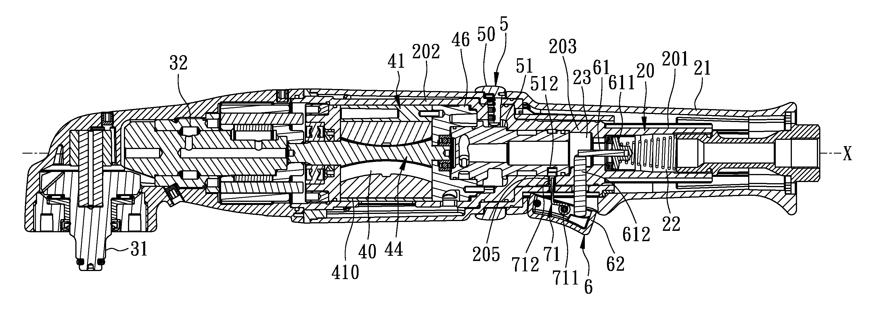
[0024]FIGS. 3 to 5 illustrate the first preferred embodiment of a pneumatic driven wrench according to the present invention. The pneumatic driven wrench includes: an outer housing 21; an inner housing 20 disposed coaxially in the outer housing 21, a tool head 31 rotatable for driving an object (not shown), a transmission unit 32 mounted in the outer housing 21 and connected to the tool head 31, a cylinder 41, a rotor 44 connected to the transmission unit 32, a first valve 611, an annular valve seat 46, a direction-switching unit 5, a valve-triggering unit 6, and a locking member 71.
[0025]The inner housing 20 has first and second sections 201, 202 and a middle section 203 disposed between and interconnecting the first and second sections 201, 202.
[0...
PUM
 Abstract
Description
Claims
Application Information