Valve assembly for a tire pressure management system

a tire pressure management and valve assembly technology, applied in the direction of vehicle maintenance, functional valve types, transportation and packaging, etc., can solve the problems of conventional wheel valves that may leak or fail, wheel valves that may not perform well at low tire pressure, and wheel valves known in the art only work over a narrow operating range of tire pressures

Active Publication Date: 2019-05-02
DANA HEAVY VEHICLE SYSTEMS GROUP LLC
View PDF5 Cites 3 Cited by
  • Summary
  • Abstract
  • Description
  • Claims
  • Application Information

AI Technical Summary

Benefits of technology

[0007]In an embodiment, the valve assembly comprises a housing having a first perforation and a second perforation. The first perforation is selectively in fluid communication with the second perforation. A shuttle assembly is provided in the housing. A failsafe piston is connected to the shuttle assembly. A first biasing member applies a bias to the failsafe piston. A second biasing member applies a bias to the shuttle assembly. When a pressure differential to between a pressure in the second perforation and a pressure in the first perforation is at or below a predetermined value, the bias applied by the first biasing member urges the failsafe piston toward the shuffle assembly to prevent fluid communication between the first perforation and the second perforation.
[0008]In another embodiment, the valve assembly comprises a housing having a first perforation and a second perforation. The first perforation is selectively in fluid communication with the second perforation. A shuttle assembly is provided in the housing. A failsafe piston is connected to the shuttle assembly via a shaft. A first biasing member applies a bias to the failsafe piston. A second biasing member applies a bias to the shuttle assembly in a direction away from the first perforation. When a pressure differential between a pressure in the second perforation and a pressure in the first perforation is at or below a predetermined value, the bias applied by the first biasing member urges the failsafe piston toward the shuttle assembly to prevent fluid communication between the first perforation and the second perforation.
[0009]The above, as well as other advantages of the embodiments will become readily apparent to those skilled in the art from the following detailed description when considered in the light of the accompanying drawings in which:

Problems solved by technology

However, the wheel valves known in the art are only effective over a narrow operating range of tire pressures.
When exposed to tire pressures greater than the aforementioned pressure, said conventional wheel valves may leak or fail.
Additionally, such wheel valves may not perform well at low tire pressures.
As another non-limiting example, when the tire, pressure is below 5 psi, conventional wheel valves may fail to close.
Such a failure may result in the tire pressure approaching 0 psi and the tire decoupling from the wheel rim.

Method used


Image

  • Valve assembly for a tire pressure management system
  • Valve assembly for a tire pressure management system
  • Valve assembly for a tire pressure management system

Examples


Embodiment Construction

[0028]It is to be understood that the invention may assume various alternative orientations and step sequences, except where expressly specified to the contrary. It is also to be understood that the specific assemblies and methods illustrated in the attached drawings, and described in the following specification are simply exemplary embodiments of the inventive concepts. Hence, specific dimensions, directions or other physical characteristics relating to the embodiments disclosed are not to be considered as limiting, unless expressly state otherwise. Also, although they may not be, like elements in various embodiments may be commonly referred to with like reference numerals within this section of the application.

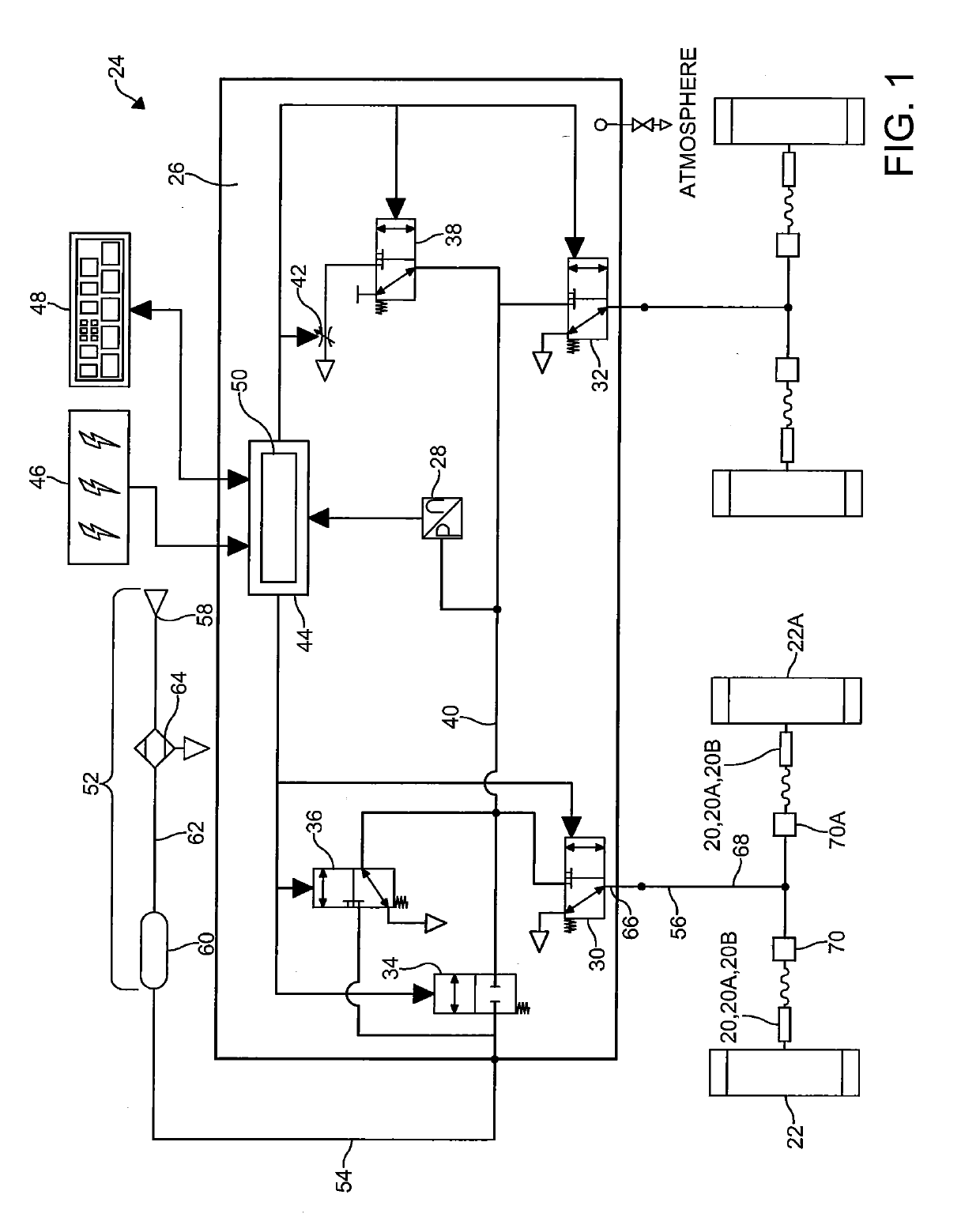
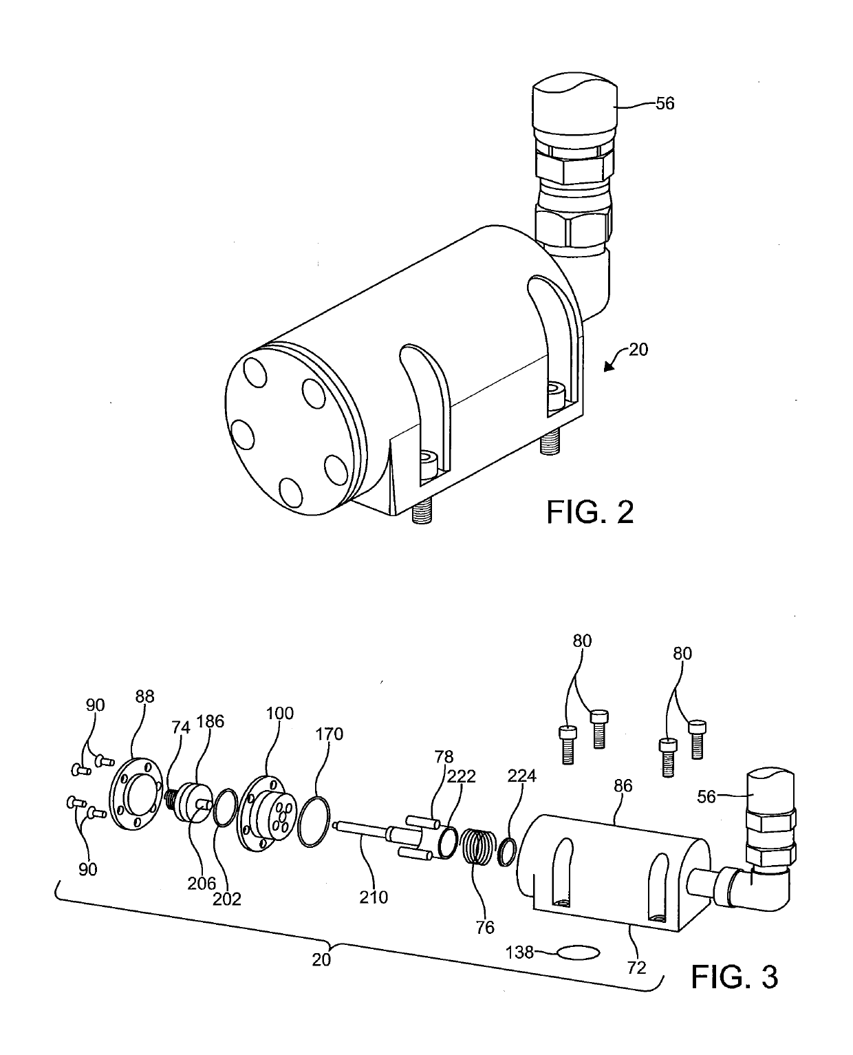
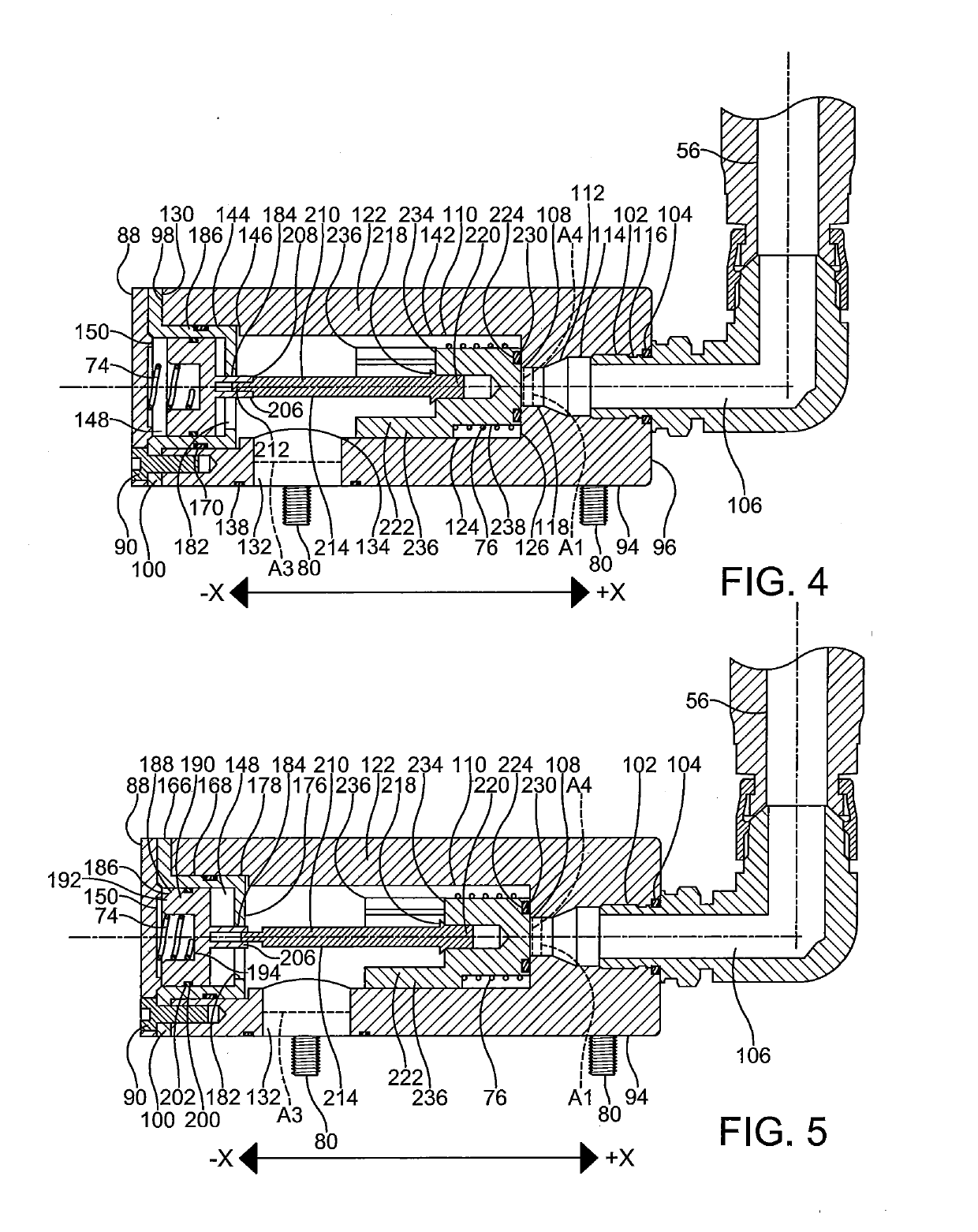
[0029]Various embodiments of a valve assembly 20, 20A, 20B are described herein. The embodiments of the valve assembly 20, 20A, 20B described herein may have applications to commercial and off-highway vehicles. Also, it would be understood by one of ordinary skill in the art...


PUM


Abstract

A valve assembly for a tire pressure management system includes a housing having a first perforation and a second perforation. The first perforation is selectively in fluid communication with the second perforation. A shuttle assembly is provided in the housing. A failsafe piston is connected to the shuttle assembly. A first biasing member applies a bias to the failsafe piston. A second biasing member applies a bias to the shuttle assembly. When a pressure differential between a pressure in the second perforation and a pressure in the first perforation is at or below a predetermined value, the bias applied by the first biasing member urges the failsafe piston toward the shuttle assembly to prevent fluid communication between the first perforation and the second perforation.

Description

CROSS-REFERENCE TO RELATED APPLICATION[0001]This application is claiming the benefit, under 35 U.S. C. 119(e), of the provisional U.S. patent application which was granted Ser. No. 62 / 322,025 and filed on Apr. 13, 2016 and the provisional U.S. patent application which was granted Ser. No. 62 / 460,030 and filed on Feb. 16, 2017, the entire disclosures of which are hereby incorporated by reference.BACKGROUND OF THE INVENTION[0002]The invention relates to a valve assembly for a tire pressure management system.[0003]Tire pressure management systems such as, for example, central tire inflation systems can be utilized to manually and / or automatically increase or decrease tire pressure. Typically, a tire pressure management system utilizes a wheel valve affixed to each wheel for effecting tire pressure adjustments. However, the wheel valves known in the art are only effective over a narrow operating range of tire pressures.[0004]As a non-limiting example, the operating range for a conventio...

Claims


Application Information

Patent Timeline
Patent Type & Authority Applications(United States)
IPC IPC(8): B60C23/00F16K17/04
CPCB60C23/003F16K17/044B60C29/06B60S5/043F16K15/207B60C23/00372B60C23/00363B60C23/00354Y10T137/3646
Inventor BALISTRERI, LUCAS A.
Owner DANA HEAVY VEHICLE SYSTEMS GROUP LLC
Why Eureka
Try Eureka