Pneumatic impact tool

a pneumatic and impact technology, applied in the direction of portable percussive tools, boring/drilling equipment, drilling machines and methods, etc., can solve the problem of time-consuming operation of maintenan

Inactive Publication Date: 2009-05-07
LAROUCHE ROCH
View PDF19 Cites 3 Cited by
  • Summary
  • Abstract
  • Description
  • Claims
  • Application Information

AI Technical Summary

Benefits of technology

[0005]According to a general aspect, there is provided a pneumatic impact tool. The pneumatic impact tool comprises: a housing defining a longitudinal passageway with a front end and a rear end, an accumulation chamber in fluid communication with the longitudinal passageway proximate to the rear end, an accumulation chamber gas port in fluid communication with the accumulation chamber, and a passageway gas port in fluid communication with the longitudinal passageway proximate to the rear end; and a piston inserted in the longitudinal passageway and movable between an impact position wherein the piston is proximate to the front end and a rest position wherein the piston is proximate to the rear end. The piston prevents fluid communication between the longitudinal passageway and the accumulation chamber and the passageway gas port is in fluid communication with the longitudinal passageway, rearwardly of the piston, in the rest position. The longitudinal passageway and the accumulation chamber are in fluid communication, in the impact position of the piston.
[0006]According to another general aspect, there is provided a method for operating an impact tool. The method comprises: maintaining a piston in a rest position proximate to a rear end of a longitudinal passageway defined in the impact tool, the piston being slidably inserted in the longitudinal passageway and preventing fluid communication between an accumulation chamber and the longitudinal passageway; inserting pressurized gas in an accumulation chamber of the impact tool; and increasing the pressure in the longitudinal passageway rearwardly of the piston, upon receiving an activation signal, the piston sliding in the longitudinal passageway from a rear position to an impact position, propulsed by the pressurized gas of the accumulation chamber.

Problems solved by technology

As it is well known, maintenance is a time consuming operation.

Method used


Image

  • Pneumatic impact tool
  • Pneumatic impact tool
  • Pneumatic impact tool

Examples


Embodiment Construction

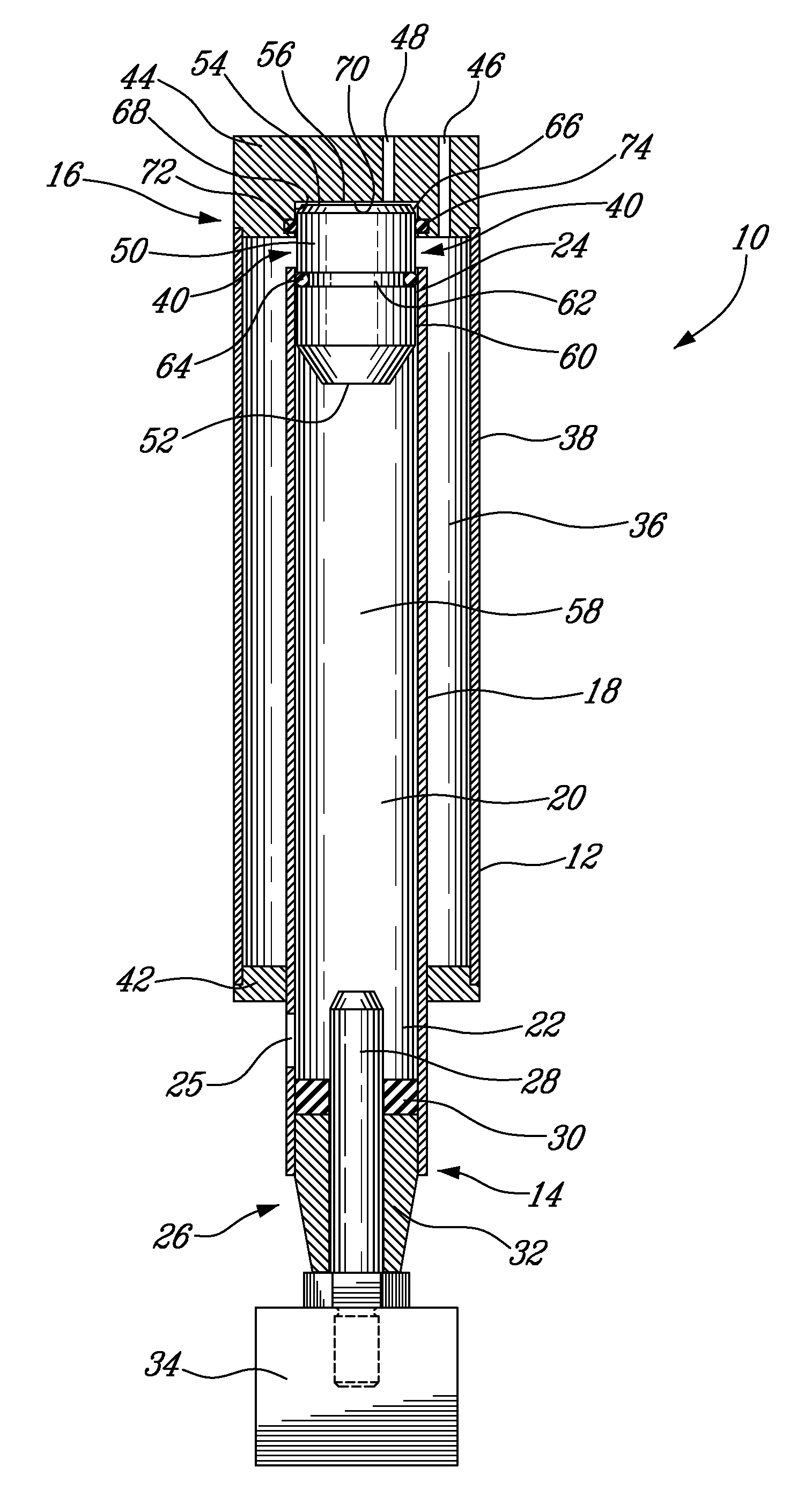
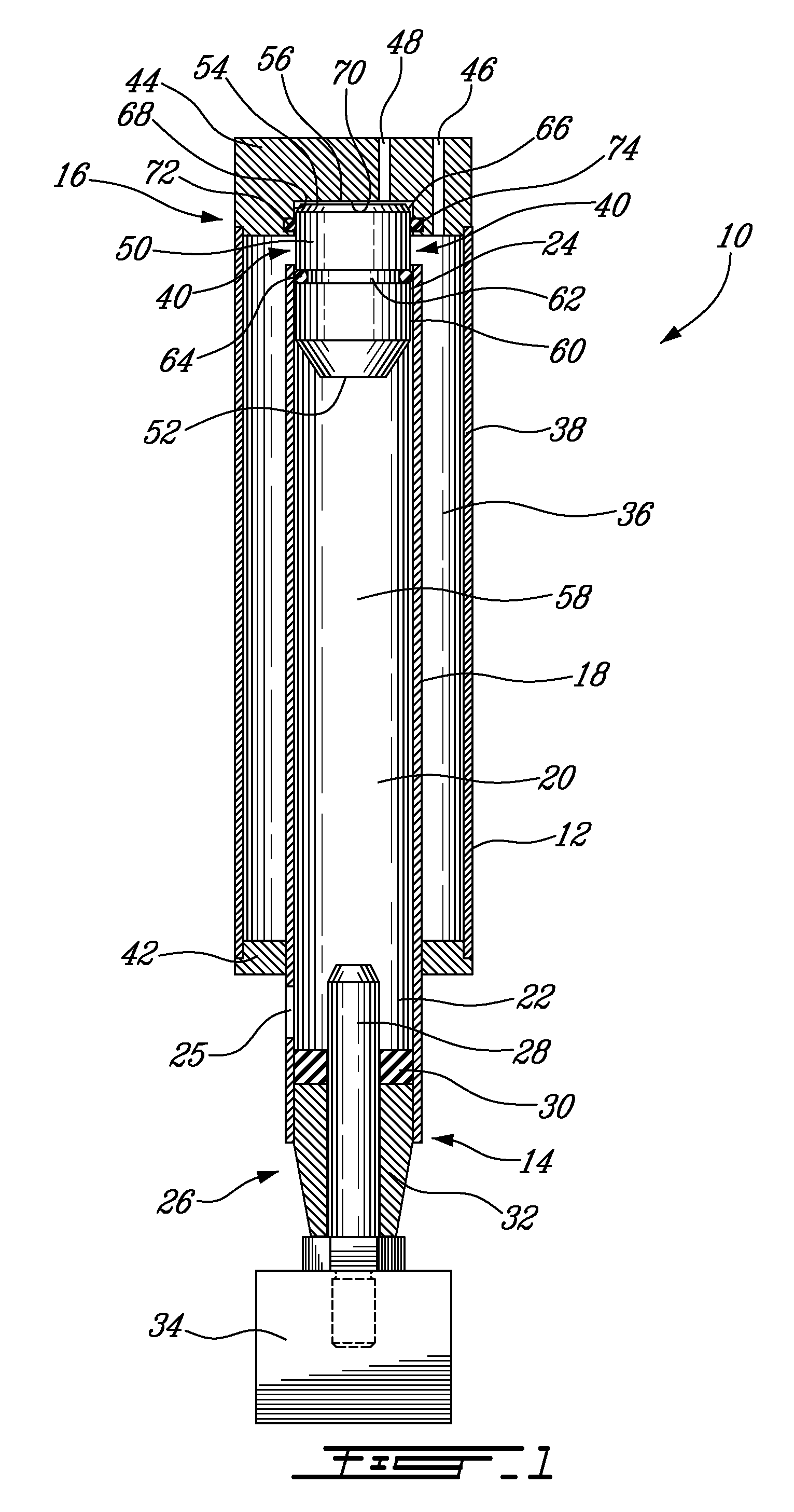
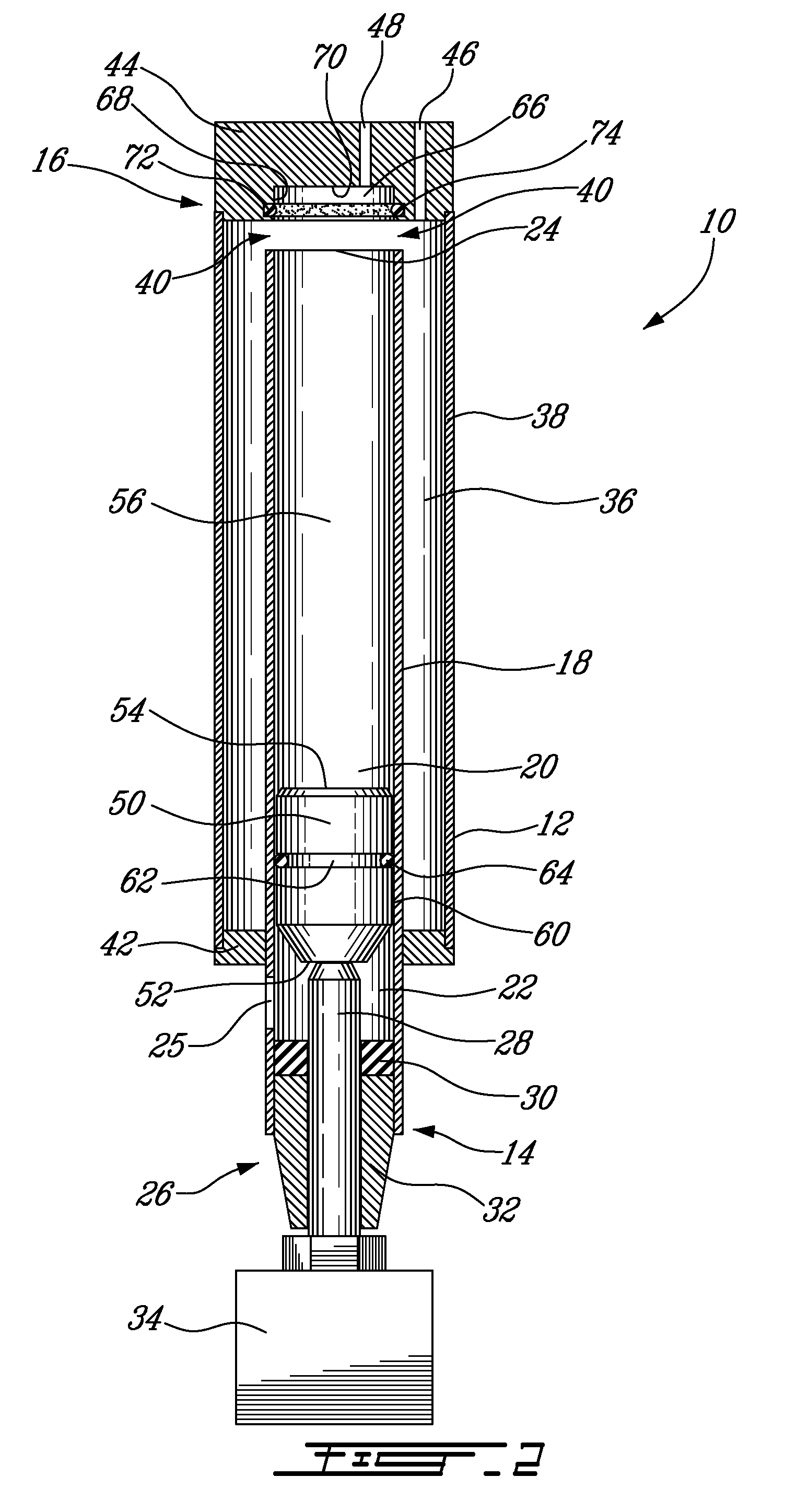
[0016]Referring now to the drawings and, more particularly, referring to FIGS. 1 and 2, it will be seen a pneumatic impact tool 10 in accordance with an embodiment. The pneumatic impact tool 10 has a housing 12 having a substantially cylindrical shape with a front end 14 and a rear end 16. The housing 12 has an inner peripheral wall 18 which defines a longitudinal passageway 20, or pathway, therein. The longitudinal passageway 20 has a cylindrical shape with a front end 22 and a rear end 24.

[0017]A vent 25 is defined in the inner peripheral wall 18 of the housing 12, proximate to the front end 22. The vent 25 allows gas to flow therethough as it will be described in greater detail below.

[0018]A head 26 is mounted to the front end 14 of the housing 12. The head 26 has a tool holder 28 extending in the longitudinal passageway 20, a damper 30, and a tool guide 32, which will be described in greater detail below. The tool holder 28 extends above the vent 25. The head 26 is adapted to re...


PUM

PropertyMeasurementUnit
pressureaaaaaaaaaa
perimeteraaaaaaaaaa
annular shapeaaaaaaaaaa

Abstract

A pneumatic impact tool includes a housing, an accumulation chamber, and a piston. The housing defines a longitudinal passageway with a rear end and a front end and a passageway gas port. The accumulation chamber has a accumulation chamber gas port connectable to a gas supply and a inner gas port in fluid communication with the longitudinal passageway. The piston is inserted in the longitudinal passageway and slides between a rest position wherein the piston is juxtaposed to the rear end of the longitudinal passageway and an impact position wherein the piston is juxtaposed to the front end of the longitudinal passageway. The piston moves from the rest position to the impact position when gas is inserted in the longitudinal passageway through the passageway gas port and is propelled therebetween by pressurized gas contained in the accumulation chamber.

Description

FIELD OF THE INVENTION[0001]The invention relates to power impact tools and, more particularly, to pneumatic impact tools.DESCRIPTION OF THE PRIOR ART[0002]Power impact tools (e.g., pneumatic, hydraulic, electric, etc.) are well known in the art and produce forces on a workpiece by direct or indirect impact of a hammer. In pneumatic impact tools, the hammer is driven by compressed air.[0003]Pneumatic impact tools have several moving parts which require continual maintenance. As it is well known, maintenance is a time consuming operation. There is thus a need for a pneumatic impact tool which will include less moving parts for reducing maintenance time and costs.BRIEF SUMMARY OF THE INVENTION[0004]It is therefore an aim of the present invention to address the above mentioned issues.[0005]According to a general aspect, there is provided a pneumatic impact tool. The pneumatic impact tool comprises: a housing defining a longitudinal passageway with a front end and a rear end, an accumul...

Claims


Application Information

Patent Timeline
Patent Type & Authority Applications(United States)
IPC IPC(8): E21B7/00B25D17/00
CPCB25D9/04B25D9/08B25D9/18B29C59/02B26D5/12B26F1/38B25D2250/371
Inventor DUVAL, MAURICE
Owner LAROUCHE ROCH
Why Eureka
Try Eureka