Fuel pump for gasoline direct injection

a fuel pump and gasoline technology, applied in the direction of fuel injecting pumps, valve details, functional valve types, etc., can solve the problems of adding further cost and high manufacturing cost of valve seats, and achieve the effect of reducing the number of components, increasing and reducing the volume of the pumping chamber

Active Publication Date: 2020-10-01
DELPHI TECH IP LTD
View PDF3 Cites 3 Cited by
  • Summary
  • Abstract
  • Description
  • Claims
  • Application Information

AI Technical Summary

Benefits of technology

[0005]Briefly described, a fuel pump in accordance with the present invention includes a fuel pump housing made of stainless steel and having an outer surface, the fuel pump housing including a pumping chamber therewithin, a plunger bore extending thereinto from the outer surface to the pumping chamber, an inlet passage extending thereinto from the outer surface to the pumping chamber which allows fuel to flow into the pumping chamber, and an outlet passage extending thereinto from the outer surface to the pumping chamber which allows fuel to flow out of the pumping chamber. The fuel pump also includes a pumping plunger which reciprocates within the plunger bore along a plunger bore axis such that an intake stroke of the pumping plunger increases volume of the pumping chamber and a compression stroke of the pumping plunger decreases volume of the pumping chamber. The fuel pump also includes an outlet valve which controls fuel flow from the pumping chamber out of the fuel pump housing. The outlet valve includes an outlet valve seating surface formed by the fuel pump housing within the outlet passage such that a nitrided layer extends from the outlet valve seating surface into the fuel pump housing. The outlet valve also includes an outlet valve member within the outlet passage, the outlet valve member being moveable between 1) a seated position in which the outlet valve member engages the outlet valve seating surface, thereby preventing fluid communication through the outlet passage and 2) an unseated position in which the outlet valve member is offset relative to the outlet valve seating surface, thereby providing fluid communication through the outlet passage. The fuel pump which includes the outlet valve seating surface formed by the fuel pump housing reduces the number of components and lowers the overall cost of manufacture.

Problems solved by technology

This valve seat is expensive to manufacture due to the material and processes involved.
This seal is typically accomplished with a press fit interface between the valve seat and the fuel pump housing where this press fit interface requires tight size tolerances and surface finish tolerances on both the valve seat and the fuel pump housing which adds further cost.

Method used


Image

  • Fuel pump for gasoline direct injection
  • Fuel pump for gasoline direct injection
  • Fuel pump for gasoline direct injection

Examples


Embodiment Construction

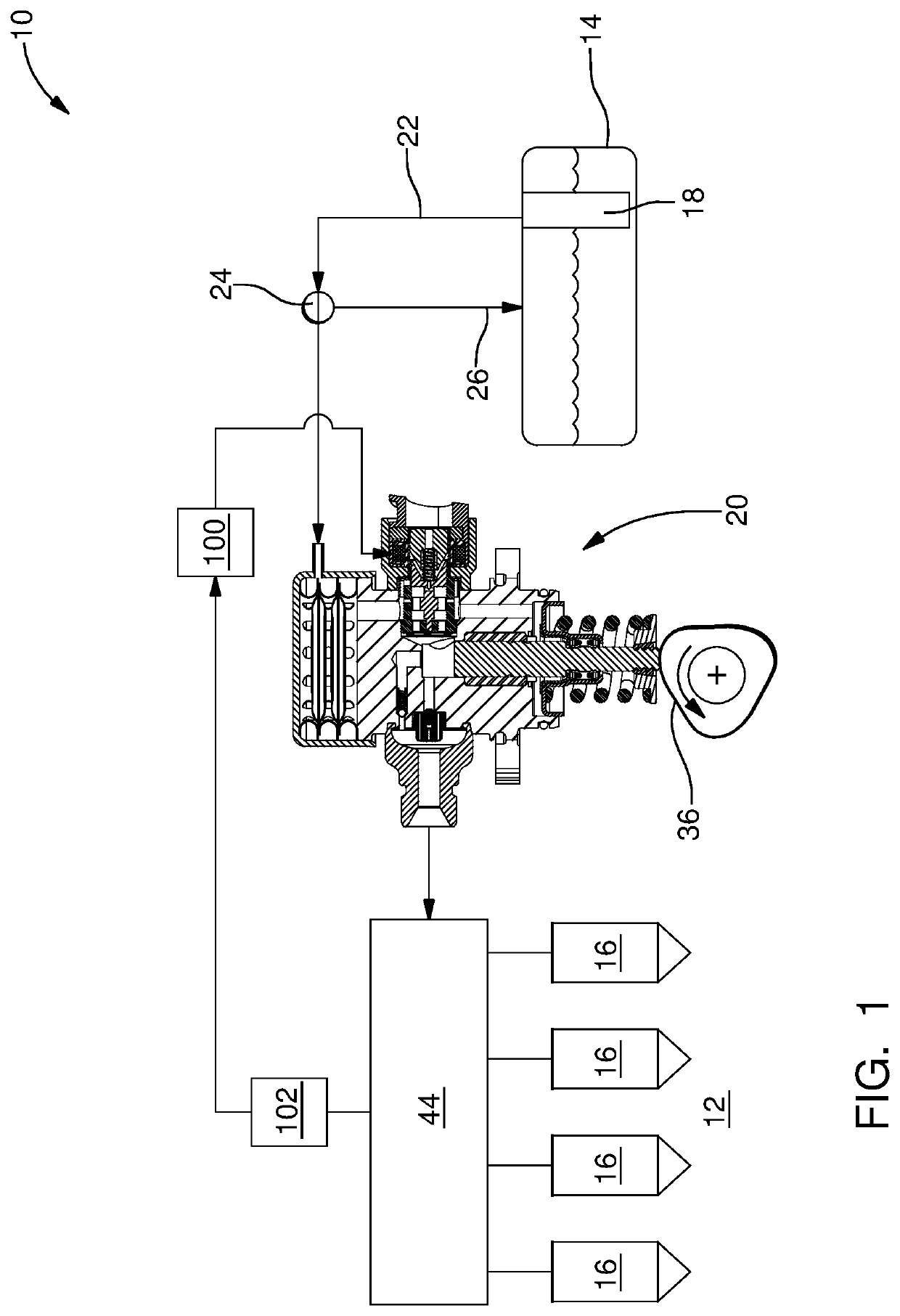
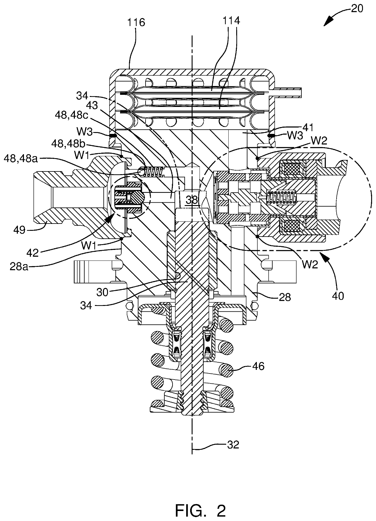
[0017]In accordance with a preferred embodiment of this invention and referring initially to FIG. 1, a fuel system 10 for an internal combustion engine 12 is shown is schematic form. Fuel system 10 generally includes a fuel tank 14 which holds a volume of fuel to be supplied to internal combustion engine 12 for operation thereof; a plurality of fuel injectors 16 which inject fuel directly into respective combustion chambers (not shown) of internal combustion engine 12; a low-pressure fuel pump 18; and a high-pressure fuel pump 20 where the low-pressure fuel pump 18 draws fuel from fuel tank 14 and elevates the pressure of the fuel for delivery to high-pressure fuel pump 20 where the high-pressure fuel pump 20 further elevates the pressure of the fuel for delivery to fuel injectors 16. By way of non-limiting example only, low-pressure fuel pump 18 may elevate the pressure of the fuel to about 500 kPa or less and high-pressure fuel pump 20 may elevate the pressure of the fuel to above...


PUM


Abstract

A fuel pump includes a fuel pump housing made of stainless steel and having a pumping chamber therewithin, a plunger bore extending thereinto, an inlet passage extending thereinto, and an outlet passage extending thereinto. A pumping plunger reciprocates within the plunger bore such that an intake stroke of the pumping plunger increases volume of the pumping chamber and a compression stroke of the pumping plunger decreases volume of the pumping chamber. An outlet valve controls fuel flow from the pumping chamber out of the fuel pump housing. The outlet valve includes an outlet valve seating surface formed by the fuel pump housing within the outlet passage such that a nitrided layer extends from the outlet valve seating surface into the fuel pump housing. The outlet valve also includes an outlet valve member within the outlet passage which is moveable between a seated position and an unseated position.

Description

TECHNICAL FIELD OF INVENTION[0001]The present invention relates to a fuel pump for gasoline direct injection, and more particularly to an outlet valve arrangement for such a fuel pump.BACKGROUND OF INVENTION[0002]Fuel systems in modern internal combustion engines fueled by gasoline, particularly for use in the automotive market, employ gasoline direct injection (GDi) where fuel injectors are provided which inject fuel directly into combustion chambers of the internal combustion engine. In such systems employing GDi, fuel from a fuel tank is supplied under relatively low pressure by a low-pressure fuel pump which is typically an electric fuel pump located within the fuel tank. The low-pressure fuel pump supplies the fuel to a high-pressure fuel pump which typically includes a pumping plunger in a fuel pump housing. The pumping plunger is reciprocated by a camshaft of the internal combustion engine in order to further pressurize the fuel in a pumping chamber of the fuel pump housing, ...

Claims


Application Information

Patent Timeline
Patent Type & Authority Applications(United States)
IPC IPC(8): F02M59/46F02M59/02F02M59/44
CPCF16K31/26F02M59/442F02M2200/26F02M59/46F16K25/005F02M59/025F16K17/0406F02M55/04F02M59/366F02M59/445F02M59/462F04B53/10
Inventor KAZOUR, YOUSSEFSPAKOWSKI, JOSEPH G.
Owner DELPHI TECH IP LTD
Why Eureka
Try Eureka