
Color image forming apparatus and method

a color image and forming apparatus technology, applied in the direction of electrographic process apparatus, instruments, optics, etc., can solve the problems of deterioration in image quality, deviations in the position of pattern images of individual colors obtained based on the detection signals of sensors, and insufficient accuracy of detection signals, so as to achieve the effect of not decreasing the printing speed of the apparatus

Inactive Publication Date: 2006-03-02
RICOH KK
View PDF7 Cites 21 Cited by
  • Summary
  • Abstract
  • Description
  • Claims
  • Application Information

AI Technical Summary

Benefits of technology

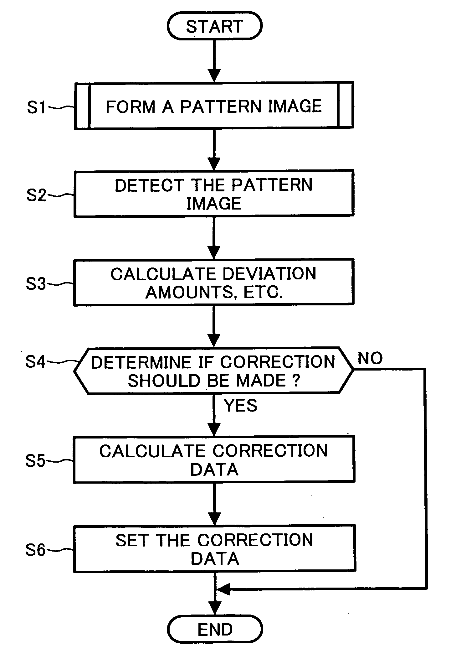
[0010] Preferred embodiments of the present invention provide a novel color image forming apparatus and a novel color image forming method in which deviations in position and errors in magnification ratio of images of individual colors that are superimposed on top of one another to form a full color image can be corrected without decreasing the printing speed of the apparatus.
[0011] The preferred embodiments of the present invention further provide a novel color image forming apparatus and a novel color image forming method in which deviations in position and errors in magnification ratio of images of individual colors that are superimposed on top of one another to form a full color image can be reliably corrected.

Problems solved by technology

If positions of images of individual colors (cyan, magenta, yellow, and black) superimposed on top of one another to form a full color image are deviated from each other, colors of a line and a character of the full color image change or irregular colors occur in the full color image, leading to deterioration in image quality.
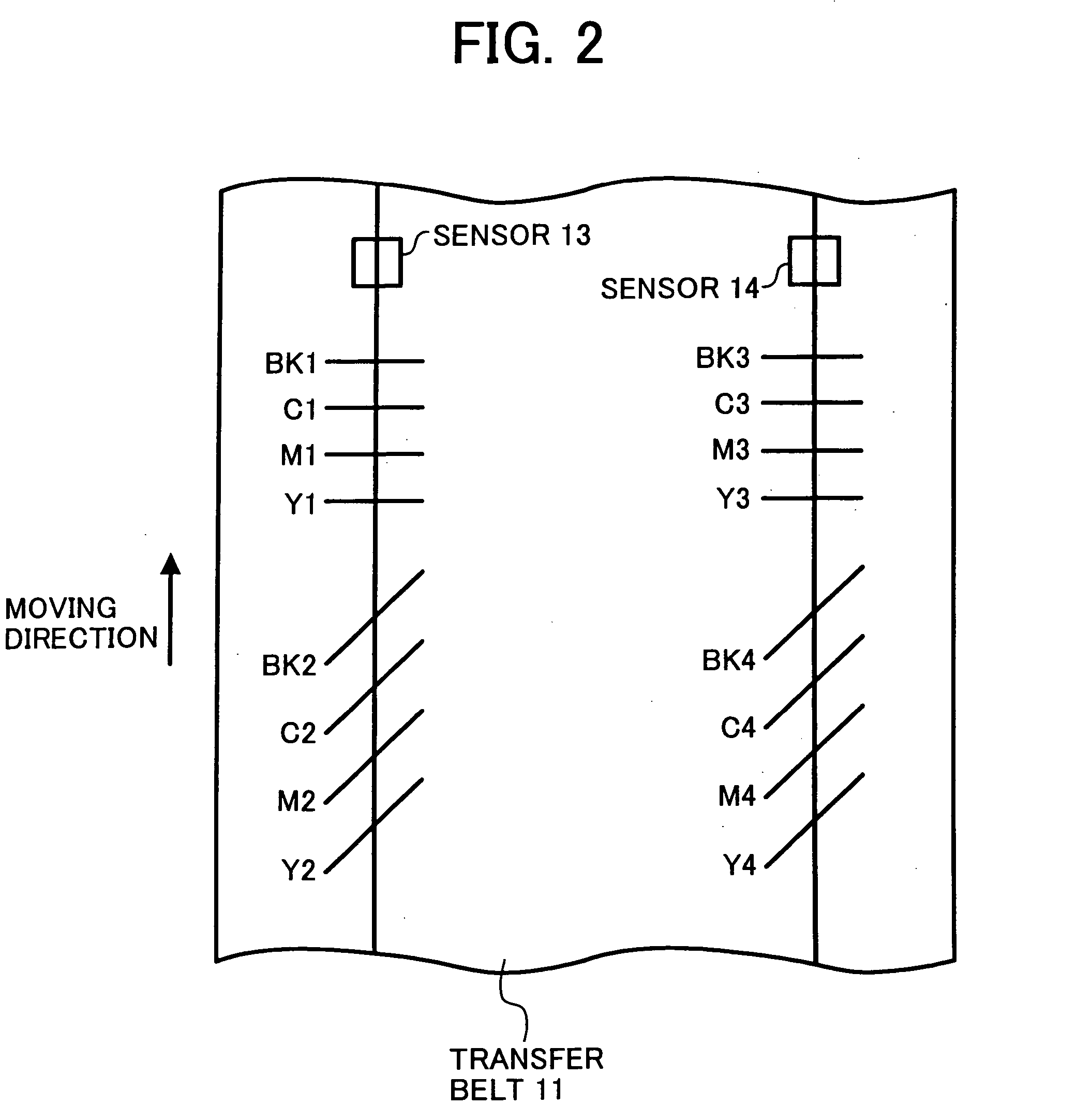
If the pattern image formed on the transfer belt is blurred or includes a thin spot, that is, if any of the straight lines and the slanted lines of the pattern of lines of the pattern image is blurred or includes a thin spot, it may occur that the amounts of deviations in position of the pattern images of individual colors obtained based upon the detection signals from the sensors are not correct.
In this case, naturally, the deviations in position of pattern images of individual colors cannot be correctly corrected, leading to deterioration in image quality.
Further, by performing the operation of correcting deviations in position of images of individual colors uselessly, the printing speed of the apparatus is decreased.

Method used


Image

  • Color image forming apparatus and method
  • Color image forming apparatus and method
  • Color image forming apparatus and method

Examples


first embodiment

[0074]FIG. 9 illustrates an operation flow of an operation of correcting deviations in position and errors in magnification ratio of images of individual colors that are superimposed on top of one another to form a full color image, according to the present invention. The operation is executed at a specified timing, e.g., every time when images for 100 pages have been formed.

[0075] After forming images of a certain number of pages (in this example, 100 pages) since the operation of correcting deviations in position and errors in magnification ratio of images of individual colors that are superimposed on top of one another to form a full color image has been performed last (S11), the pattern image for checking illustrated in FIG. 8 is formed on the transfer belt 111 as described above, at a part of the transfer belt 11 between parts of the transfer belt 11 conveying recording sheets, respectively, i.e., between a part of the transfer belt 11 conveying a recording sheet on which an im...

second embodiment

[0083]FIG. 11A and FIG. 11B illustrate an operation flow of an operation of correcting deviations in position and errors in magnification ratio of images of individual colors that are superimposed on top of one another to form a full color image, according to the The operation differs from that of the previous embodiment in that when it has been determined that deviations in position and errors in magnification ratio of images of individual colors that are superimposed on top of one another to form a full color image cannot be correctly corrected, after forming images of a predetermined quantity, whether or not deviations in position and errors in magnification ratio of images of individual colors can be correctly corrected is determined again by forming the pattern image for checking and by determining if the width of each line of the pattern of line of the pattern image for checking is equal to or greater than the reference value. Image forming conditions of the apparatus sometim...

third embodiment

[0092]FIG. 13 illustrates an exemplary construction of the LD controller 22 according to the The LD controller 22 includes the LD drive device 51 configured to control the light quantity of the LD of each optical beam scan device 6 and a PWM (pulse width modulation) signal generation device 52 configured to control the lighting timing of the LD. The PWM signal generation device 52 outputs a PWM signal to the LD drive device 51 according to image data and a control signal 1 input from the printer controller 24, and the LD drive device 51 lights the LD of a corresponding optical scan device 6 for a period of time corresponding to the PWM signal. Further, by inputting the forced LD lighting signal BD from the synchronization detect lighting controller 19 into the LD drive device 51, the LD is lit for a period of time corresponding to the forced LD lighting signal BD. A value for setting a light quantity of the LD when the LD is lit is set in a register at the LD drive device 51 by a c...


PUM


Abstract

A color image forming apparatus forming a full color image by superimposing images of individual colors includes a correction possibility determination device to determine whether or not deviations in position and errors in magnification ratio of images of individual colors that are superimposed on top of one another to form a full color image can be correctly performed and a correction device to perform the operation of correcting deviations in position and errors in magnification ratio of individual colors that are superimposed on top of one another to form a full color image. The operation of correcting deviations in position and errors in magnification ratio of individual colors that are superimposed on top of one another to form a full color image is performed by the correction device when the correction possibility determination device has determined that deviations in position and errors in magnification ratio of images of individual colors that are superimposed on top of one another to form a full color image can be correctly corrected.

Description

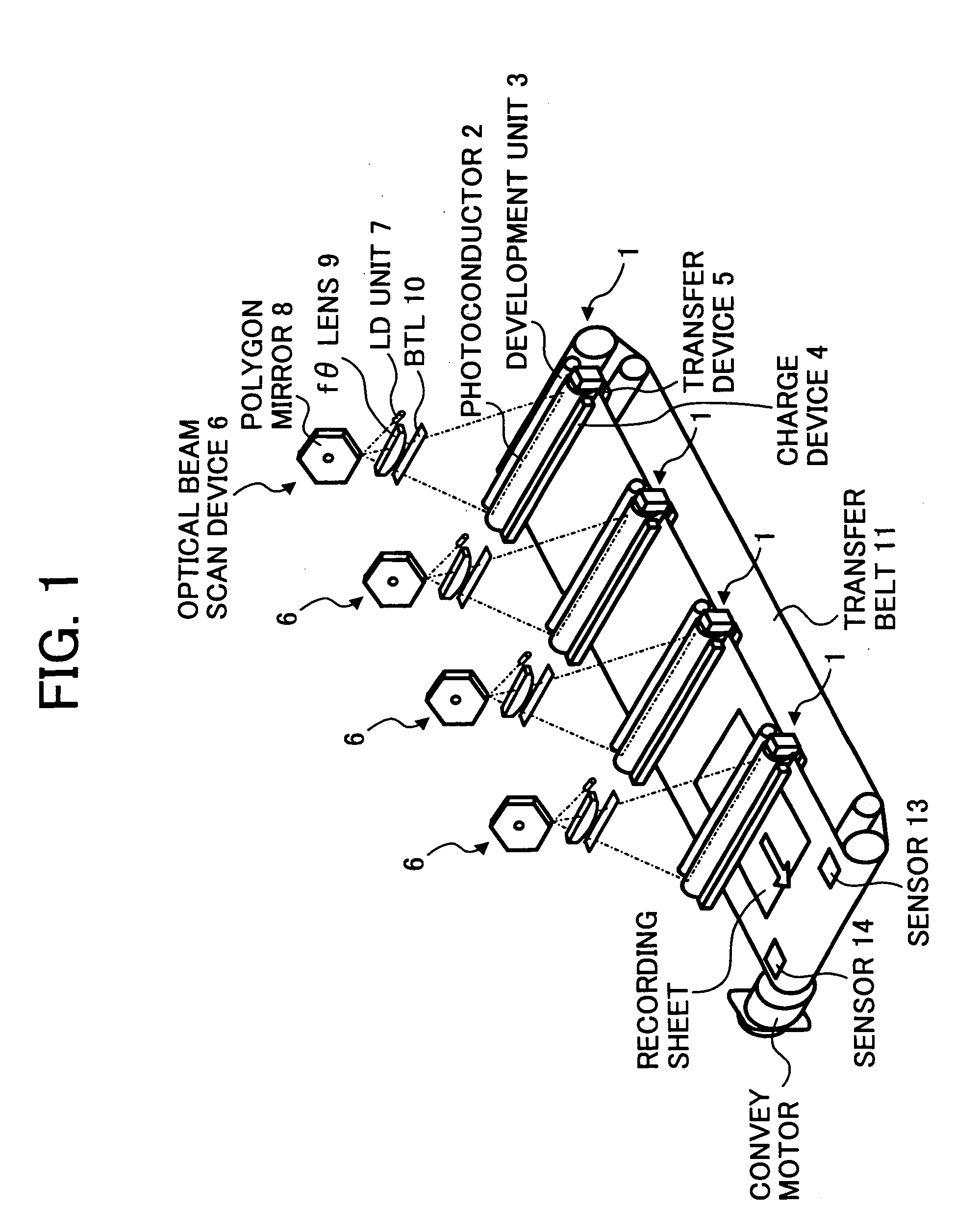
CROSS-REFERENCE TO RELATED DOCUMENTS [0001] The present application claims priority and contains subject matter related to Japanese Patent Applications No. 2003-050131, No. 2003-056433, and No. 2003-431387 filed in the Japanese Patent Office on Feb. 26, 2003, Mar. 3, 2003 and Dec. 25, 2003, respectively, and the entire contents of each of which are hereby incorporated herein by reference. BACKGROUND OF THE INVENTION [0002] 1. Field of the Invention [0003] The present invention relates to a color image forming apparatus, such as a color copier, a color printer, a color facsimile apparatus, a color printing apparatus, etc., forming a full color image by superimposing images of individual colors on top of one another, and in particular relates to control of aligning positions of images of individual colors that are superimposed on top of one another to form a full color image. [0004] 2. Description of the Background Art [0005] In a color image forming apparatus forming a full color ima...

Claims


Application Information

Patent Timeline
Patent Type & Authority Applications(United States)
IPC IPC(8): G03G15/01G03G15/00G03G15/04G03G15/043G03G15/06G03G15/08G03G15/16G03G21/14
CPCG03G15/0178G03G2215/0161G03G2215/00059G03G15/0194G03G15/5058
Inventor MAEDA, KATSUHIKO
Owner RICOH KK
Learn More