Cable end connector having a latching device and an unlatching actuator
- Summary
- Abstract
- Description
- Claims
- Application Information
AI Technical Summary
Benefits of technology
Problems solved by technology
Method used
Image

Examples
Embodiment Construction
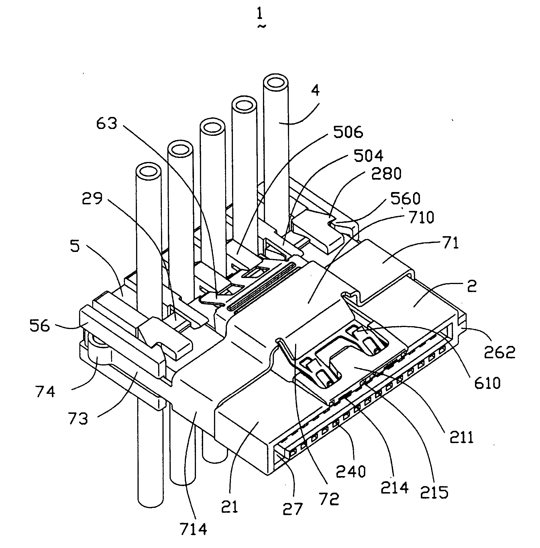
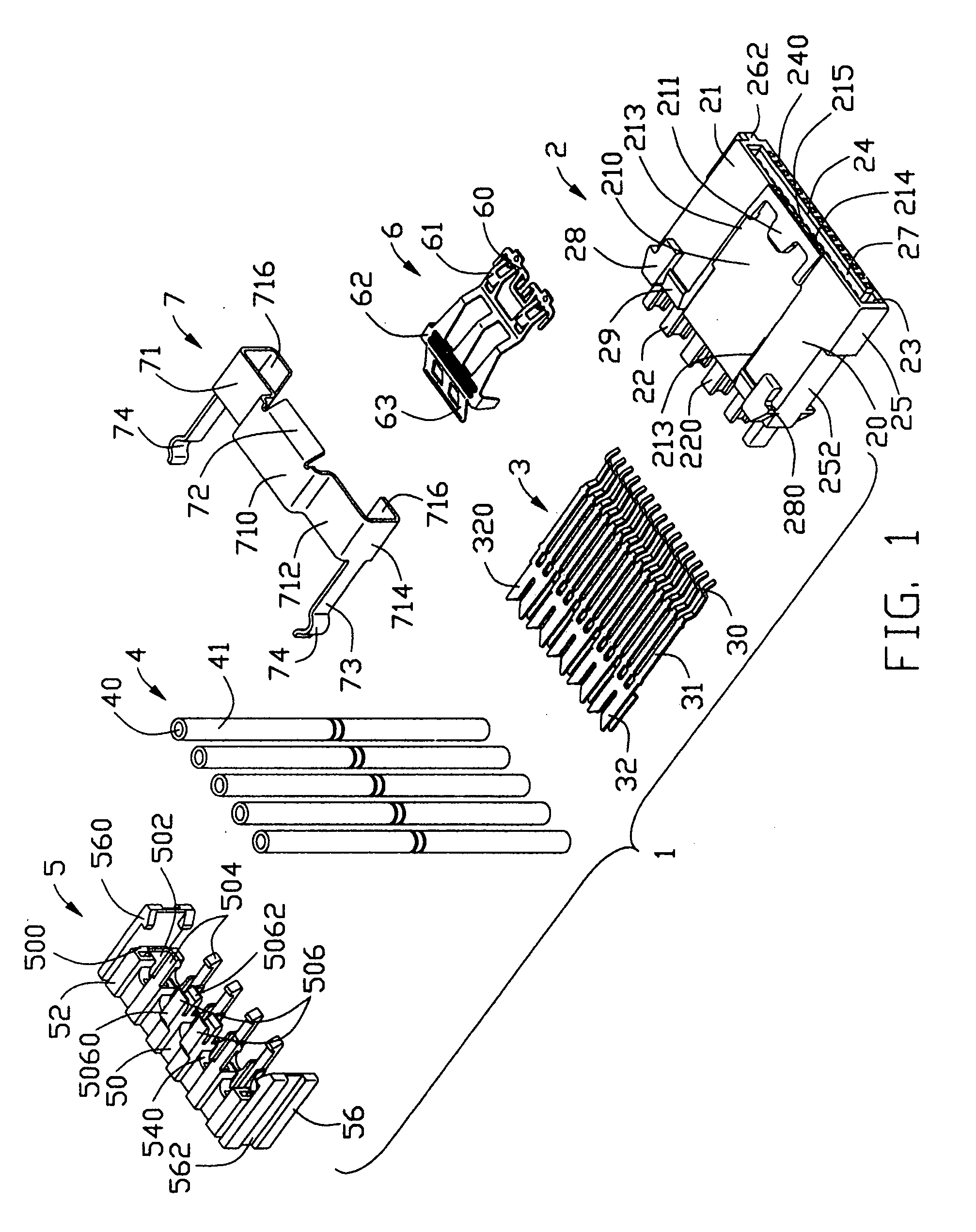
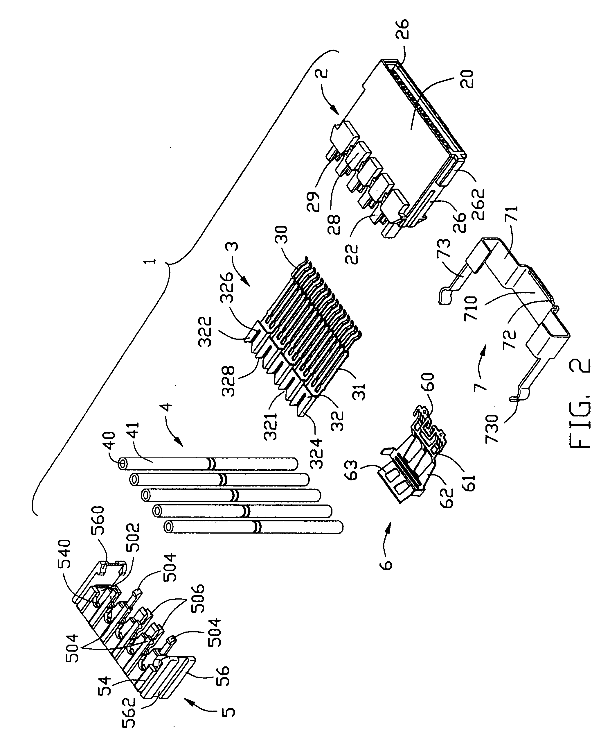
[0021] Referring to FIGS. 1-4, a cable end connector 1 in accordance with the present invention comprises an insulative housing 2, a plurality of contacts 3, a plurality of wires 4, an insulative cover 5, a latching device 6 and a unlatching actuator 7. In a preferred embodiment, the cable end connector 1 is a power cable end connector.
[0022] The insulative housing 2 comprises a front engaging portion 20 and a rear terminating portion 22. The front engaging portion 20 comprises an upper wall 21, a lower wall 23 opposite to the upper wall 21, and a pair of first and second sidewalls 25, 26 connecting with the upper wall 21 and the lower wall 23. The first sidewall 25 defines a recess 252 at a rear portion thereof. The second sidewall 26 forms a guiding projection 262 projecting outwardly for guiding a proper insertion of a complementary connector. An L-shaped receiving space 27 is defined between the upper and the lower walls 21, 23. A block 24 is formed on the lower wall 23 and pro...
PUM
 Abstract
Description
Claims
Application Information
 - R&D Engineer
- R&D Manager
- IP Professional
- Industry Leading Data Capabilities
- Powerful AI technology
- Patent DNA Extraction
Browse by: Latest US Patents, China's latest patents, Technical Efficacy Thesaurus, Application Domain, Technology Topic.
© 2024 PatSnap. All rights reserved.Legal|Privacy policy|Modern Slavery Act Transparency Statement|Sitemap