Tool box having a locking mechanism

a tool box and locking mechanism technology, applied in the field of tool boxes, can solve the problems of reducing the lifetime of the conventional tool box and inconvenience for users, and achieve the effect of convenient and convenient opening of the tool box

Active Publication Date: 2006-03-09
LEE YI MIN
View PDF22 Cites 56 Cited by
  • Summary
  • Abstract
  • Description
  • Claims
  • Application Information

AI Technical Summary

Benefits of technology

[0006] Another objective of the present invention is to provide a tool box, wherein the locking mechanism is operated to open the tool box automatically, so that a user can open the tool box easily and conveniently, thereby facilitating the user operating the locking mechanism to open the tool box.
[0007] A further objective of the present invention is to provide a tool box, wherein the snapping member of the snapping unit is detached from the locking block of the locking unit automatically, so that the user detaches the snapping unit from the locking unit easily and conveniently, thereby greatly facilitating the user detaching the first casing from the second casing so as to open the tool box.

Problems solved by technology

However, the snapping plate of the cover is easily loosened from the snapping recess of the main body, so that the cover is not combined with the main body rigidly and stably, thereby greatly causing inconvenience to a user.
In addition, the snapping plate of the cover is easily worn out during a long-term utilization, thereby decreasing the lifetime of the conventional tool box.

Method used


Image

  • Tool box having a locking mechanism
  • Tool box having a locking mechanism
  • Tool box having a locking mechanism

Examples


Embodiment Construction

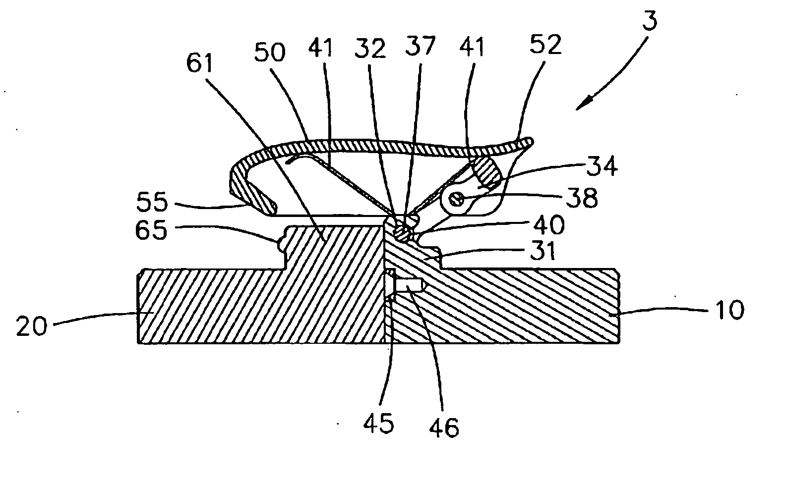
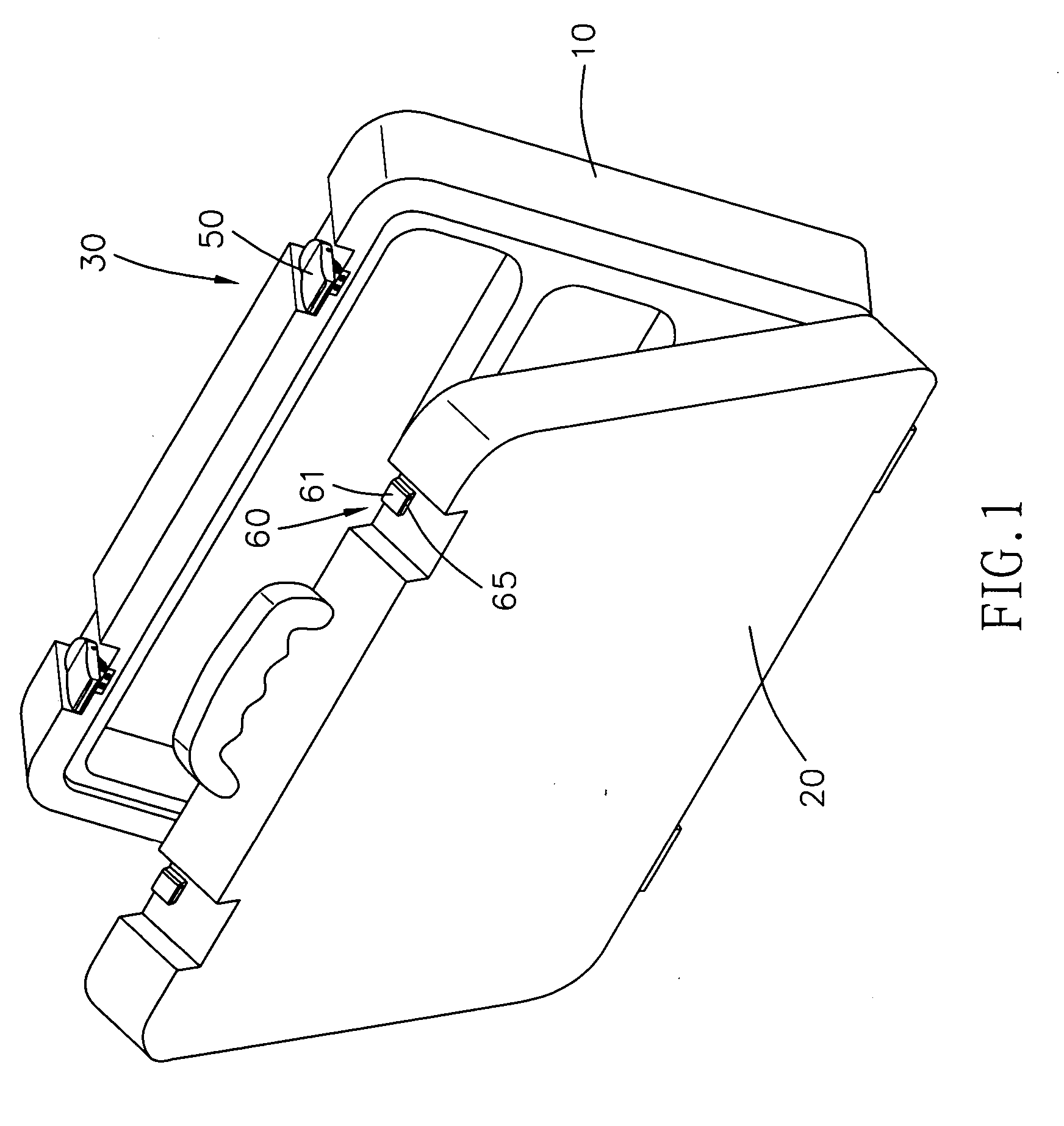
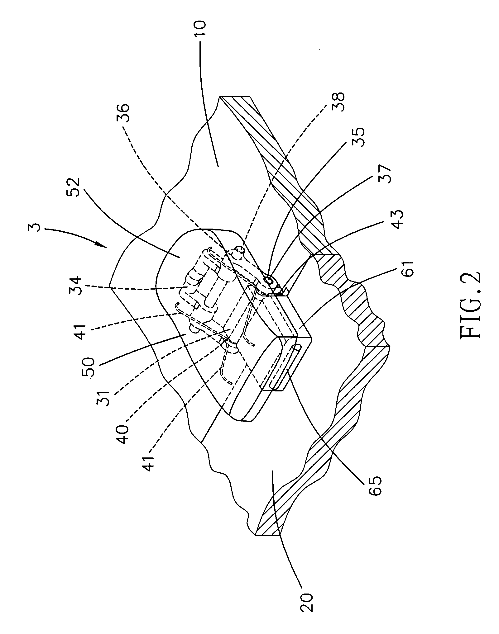
[0019] Referring to the drawings and initially to FIGS. 1-4, a tool box in accordance with the preferred embodiment of the present invention comprises a first casing 10, a second casing 20 pivotally mounted on the first casing 10, and a locking mechanism 3 mounted between the first casing 10 and the second casing 20 to combine the first casing 10 and the second casing 20.

[0020] The locking mechanism 3 includes a locking unit 60 mounted on the second casing 20, and a snapping unit 30 mounted on the first casing 10 and detachably locked on the locking unit 60.

[0021] The locking unit 60 of the locking mechanism 3 includes a locking block 61 mounted on a periphery of the second casing 20 and having a side formed with a semi-circular protruding locking rib 65.

[0022] The snapping unit 30 of the locking mechanism 3 includes a seat 31 mounted on a periphery of the first casing 10, a pivot member 34 pivotally mounted on the seat 31, a snapping member 50 having a first portion pivotally mo...


PUM


Abstract

A tool box includes a first casing, a second casing, and a locking mechanism. The locking mechanism includes a locking unit, and a snapping unit. The locking unit includes a locking block. The snapping unit includes a seat, a pivot member, a snapping member, and two torsion springs. Thus, the locking mechanism is operated to open the tool box automatically, so that a user can open the tool box easily and conveniently, thereby facilitating the user operating the locking mechanism to open the tool box.

Description

BACKGROUND OF THE INVENTION [0001] 1. Field of the Invention [0002] The present invention relates to a tool box, and more particularly to a tool box having a locking mechanism. [0003] 2. Description of the Related Art [0004] A conventional tool box comprises a main body formed with a snapping recess, and a cover pivotally mounted on the main body and formed with a snapping plate snapped into the snapping recess of the main body to lock the cover on the main body. However, the snapping plate of the cover is easily loosened from the snapping recess of the main body, so that the cover is not combined with the main body rigidly and stably, thereby greatly causing inconvenience to a user. In addition, the snapping plate of the cover is easily worn out during a long-term utilization, thereby decreasing the lifetime of the conventional tool box. SUMMARY OF THE INVENTION [0005] The primary objective of the present invention is to provide a tool box having a locking mechanism. [0006] Another...

Claims


Application Information

Patent Timeline
Patent Type & Authority Applications(United States)
IPC IPC(8): E05C19/06
CPCA45F2200/0575B25H3/02Y10T24/2143Y10S292/48Y10T24/2196Y10S292/49Y10T24/2145Y10T292/0894Y10T292/09Y10T292/0871
Inventor LEE, YI-MIN
Owner LEE YI MIN
Why Eureka
Try Eureka