Piezoelectric user interface

a user interface and piezoelectric technology, applied in the field of piezoelectric user interfaces, can solve the problems of annoying “beep” generated in connection with each keystroke, the space required by the mechanism, and the large amount of space required by the mechanism, and achieve the effect of improving the means of generating tactile feedback

Active Publication Date: 2006-03-09
NOKIA TECHNOLOGLES OY
View PDF12 Cites 62 Cited by
  • Summary
  • Abstract
  • Description
  • Claims
  • Application Information

AI Technical Summary

Benefits of technology

[0007] An object of the present invention is to solve the above-mentioned problems and to provide an apparatus with improved means for generating tactile feedback to a user in connection with a keystroke.
[0010] The invention is based on the idea of utilizing a piezoelectric element in an apparatus in order to provide the user with tactile feedback in connection with a keystroke. The piezoelectric element is small enough to be integrated such an element into a membrane keypad of an apparatus, for instance. A piezoelectric element can be controlled to create vibration which propagates to the key pressed by a user. The space needed in the prior art solutions for a mechanism to produce a suitable “click” at each keystroke can be significantly minimized by the invention, since the piezoelectric element can create vibration where the key which has been pressed is pushed back in a direction towards a finger of the user.
[0011] The most significant advantages of the present invention are that tactile feedback can be generated employing a simpler solution which requires less space than the prior art solutions, the energy consumption in connection with generating tactile feedback is low, and that the price of the means necessary for generating tactile feedback is relatively low.
[0012] In a first preferred embodiment the present invention, the apparatus includes a controller arranged to identify a key in said keypad pressed by the user, and to check whether or not the pressed key has been available as an option at that particular moment. If the key has been available as an option, a piezoelectric element is controlled to generate first kind of vibration. If, on the other hand, the key has not been available as an option, a piezoelectric element is controlled to generate second kind of vibration. This embodiment makes it possible to give the user such tactile feedback that the user can immediately feel whether the user has pressed a “right” key or a “wrong” key.
[0013] In a second preferred embodiment, the apparatus is a media terminal comprising means for establishing telecommunication connections, and the apparatus is arranged to generate an alerting sound signal with said at least one piezoelectric element in response to an incoming call. This embodiment is advantageous as it makes it possible to save space in the media terminal, since the alerting sound signal can be created with the same piezoelectric element as is used to generate tactile feedback when a key is pressed. This can be achieved when the media terminal is programmed to feed such a signal to the piezoelectric element that the piezoelectric element generates vibration that can be heard.
[0014] In a third preferred embodiment, the apparatus is a media terminal comprising means for establishing telecommunication connections, and said apparatus is arranged to generate an alerting vibration signal with said at least one piezoelectric element in response to an incoming call. This embodiment makes it possible to save space by eliminating an extra component used in the prior art media terminals in order to accomplish vibration alerting. Instead, it is possible to generate such vibration alert by using the same piezoelectric element as is used to generate tactile feedback when a key is pressed. In this embodiment, it might be advantageous to have several piezoelectric elements in the media terminal since this makes it possible to generate very strong vibration. The user thus feels the vibration even if the media terminal is located in a pocket.

Problems solved by technology

The problem with such prior art mechanical solutions is the space required by the mechanism.
The space required by the movement and the space required by the mechanism itself mean that the entire keypad turns out to be relatively thick.
The problem with this prior art solution is, however, that the “beep” generated in connection with each keystroke is rather annoying, and most users would thus prefer to turn off such a “beep”.
This, however, is not possible in practice because then the user will not know when a keystroke has been registered, since this solution does not give any tactile feedback to the user.

Method used


Image

  • Piezoelectric user interface
  • Piezoelectric user interface
  • Piezoelectric user interface

Examples


Embodiment Construction

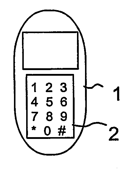
[0028]FIGS. 1a to 1c illustrate a first preferred embodiment of the invention. The apparatus 1 in the example of FIGS. 1a to 1c is a media terminal comprising means for establishing telecommunication connections. These means include a radio transmitter and a radio receiver for establishing, for instance, phone calls via a cellular mobile communication system. The mobile communication system may be, for instance, a GSM system (Global System for Mobile communications) or a third generation mobile communication system.

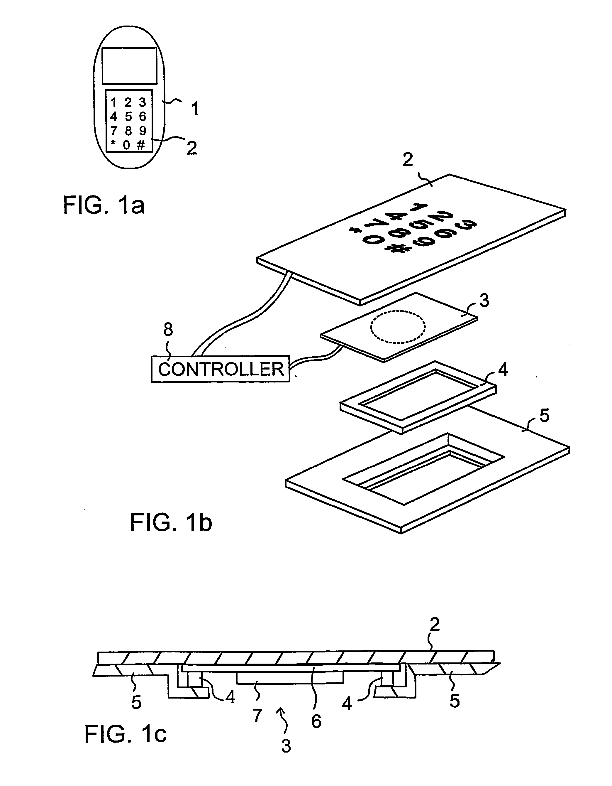
[0029]FIG. 1a shows an apparatus comprising a keypad 2 and a display. FIG. 1b shows an exploded view of parts associated with the keypad 2 of the apparatus 1 in FIG. 1a, and FIG. 1c shows a sectional view of the parts in FIG. 1b. The keypad 2 is a flexible membrane keypad which may consist of one layer (as shown in the FIGS. 1b and 1c) or of several cooperating layers. The locations of the keys are visible on an upper side of the keypad 2. When a user presses one of the ...


PUM


Abstract

The invention relates to an apparatus (1) comprising a keypad (2), and means for generating a tactile response to a user of the apparatus when a key in said keypad is pressed. In order accomplish a simple construction requiring a minimum of space, said means for generating a tactile response include at least one piezoelectric element (3) arranged to generate vibration which is forwarded to the user via a key when said key is pressed.

Description

BACKGROUND OF THE INVENTION [0001] 1. Field of the Invention [0002] This invention relates to a solution for generating tactile feedback to a user of an apparatus when the user presses a key on a keypad of the apparatus. Such tactile feedback, which is perceptible by touch, makes it possible for the user to know when the key has been pressed long and hard enough for the apparatus to register the keystroke. [0003] 2. Description of the Prior Art [0004] Several different solutions are previously there known for indicating to a user of an apparatus that a key has been pressed long and hard enough to enable the keystroke to be registered. [0005] A previously known solution is to provide each key with a mechanism which produces a “click” that can be felt and / or heard by a user when the user presses a key. The problem with such prior art mechanical solutions is the space required by the mechanism. It is in practice necessary to design the key such that the key is allowed to move a predete...

Claims


Application Information

Patent Timeline
Patent Type & Authority Applications(United States)
IPC IPC(8): H04M1/00H04M9/00H04B1/38G06F3/02B06B1/02B06B1/06B41J5/08H01H13/84H01L41/09H03K17/96
CPCB06B1/0215G06F3/016G06F3/0202H03K2217/96062H01H2215/052H03K17/96H01H13/84G10K9/122G10K9/121G06F3/0488G10K9/125G10K9/00G10K9/12H04M19/02H04W68/00G08B3/10G08B6/00G08B7/06
Inventor TUOVINEN, JUHANI
Owner NOKIA TECHNOLOGLES OY
Why Eureka
Try Eureka