Power generation system and method of operating same

a power generation system and power generation technology, applied in the direction of machines/engines, energy input, mechanical equipment, etc., can solve the problems of excess power generation capacity, large electricity consumption of business and consumers,

Inactive Publication Date: 2006-03-16
GENERAL ELECTRIC CO
View PDF21 Cites 108 Cited by
  • Summary
  • Abstract
  • Description
  • Claims
  • Application Information

AI Technical Summary

Problems solved by technology

Businesses and consumers consume large amounts of electricity.
As a result, a typical power provider, such as an electrical utility, has excess power generating capacity during non-peak operating periods, such as the late evening or early morning.

Method used


Image

  • Power generation system and method of operating same
  • Power generation system and method of operating same
  • Power generation system and method of operating same

Examples


Embodiment Construction

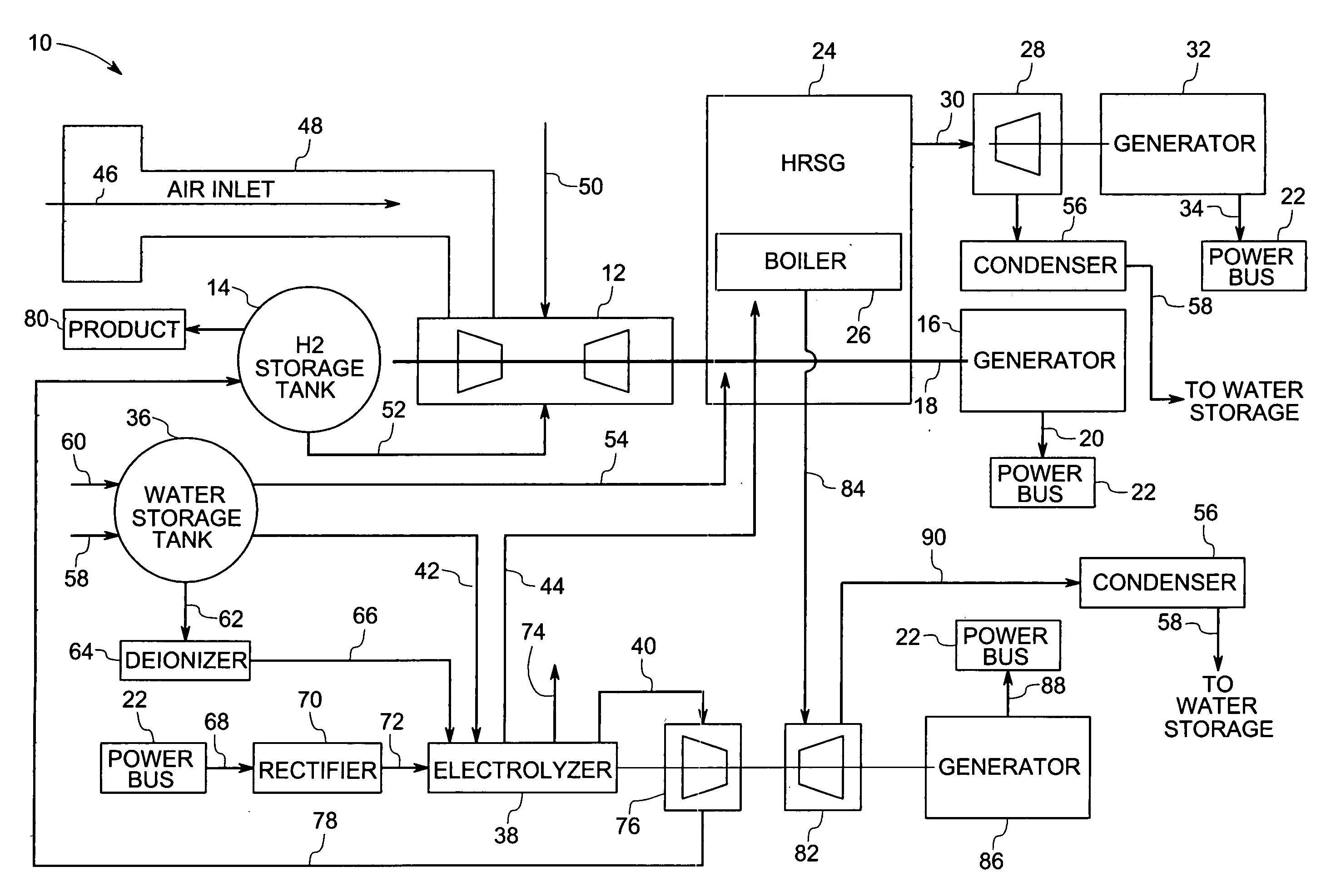
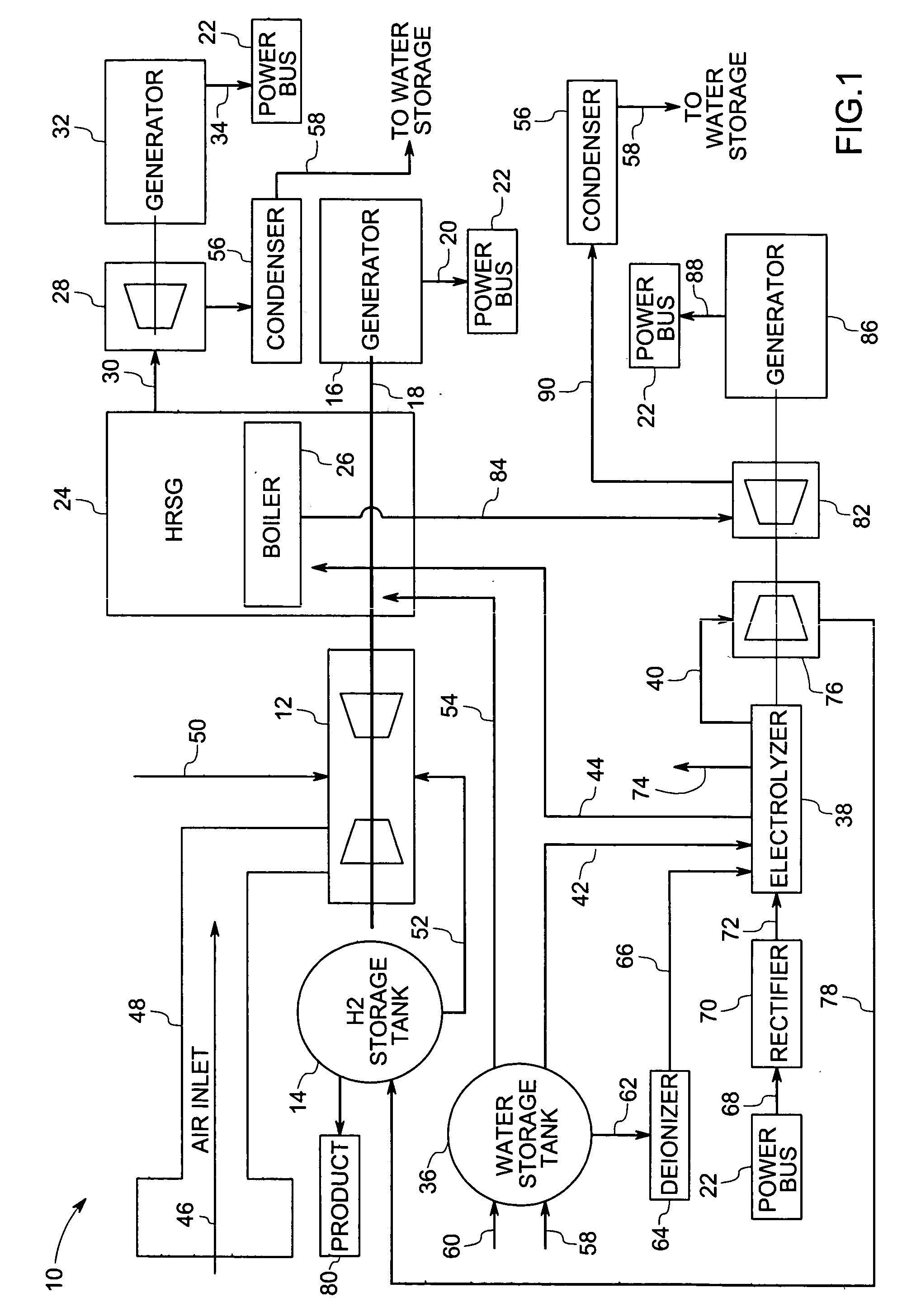
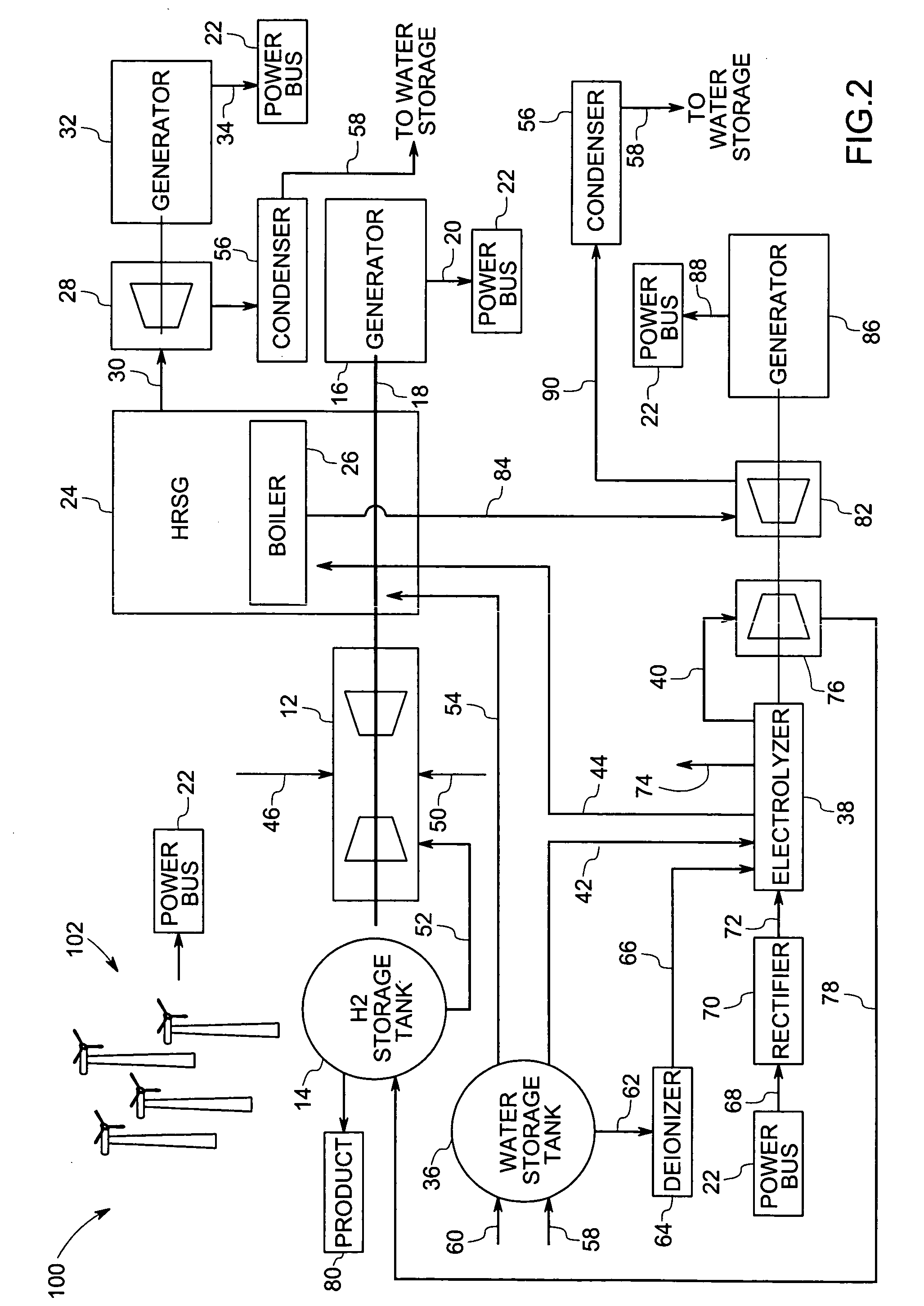
[0012] Referring now to FIG. 1, a power generation system, represented generally by reference numeral 10, is illustrated. The power generation system 10 comprises a gas turbine 12, a hydrogen storage tank 14, and an electrical generator 16 operable to generate electrical power from the mechanical power produced by the gas turbine 12. It should be noted that, other types of heat engines, such as a reciprocating hydrogen engine, may be used instead of the gas turbine 12. The generator 16 is coupled to the gas turbine 12 via a shaft 18. In the illustrated embodiment, the electrical power generated by the generator 16, represented by the arrow 20, is coupled to a power bus 22 for distribution to an electrical grid.

[0013] In addition, the illustrated embodiment of the power generation system 10 comprises a heat recovery steam generator (HRSG) 24. However, other types of steam production devices may be used. The heat recovery steam generator 24 receives hot combustion products from the g...


PUM


Abstract

A power generation system comprising a liquid-cooled electrolyzer operable to produce a supply of hydrogen from water is provided. The power generation system may also comprise a steam turbine and a steam production device operable to produce a supply of steam to the steam turbine. The power generation system may also comprise a system operable to provide cooling liquid to the liquid-cooled electrolyzer and to couple heated cooling liquid from the liquid-cooled electrolyzer to the steam production device.

Description

BACKGROUND [0001] The invention relates generally to the field of power generation systems and, more particularly, to a combined cycle power generation system for production of hydrogen. [0002] Businesses and consumers consume large amounts of electricity. Some businesses produce electricity for sale or for their own use. Other businesses and consumers purchase electricity from a utility. The amount of electricity that is consumed may vary over the course of a day and over the course of a year. For example, overall electrical demand typically peaks in the late afternoon in the summer due to the high demand for power to run air conditioning systems. Electrical demand typically is lower in the winter and the late evening or early morning when temperatures are cooler and / or people are asleep. However, a power provider, such as a utility, must be able to provide sufficient power generating capacity to meet the peak demand. As a result, a typical power provider, such as an electrical uti...

Claims


Application Information

Patent Timeline
Patent Type & Authority Applications(United States)
IPC IPC(8): F01K23/06
CPCC25B1/04Y02E60/366F01K23/064C25B15/08Y02E60/36Y02P20/129Y02P20/133
Inventor BOURGEOIS, RICHARD SCOTT
Owner GENERAL ELECTRIC CO
Why Eureka
Try Eureka