

Image display apparatus
- Summary
- Abstract
- Description
- Claims
- Application Information
AI Technical Summary
Benefits of technology
Problems solved by technology
Method used
Image

Examples
embodiment 1
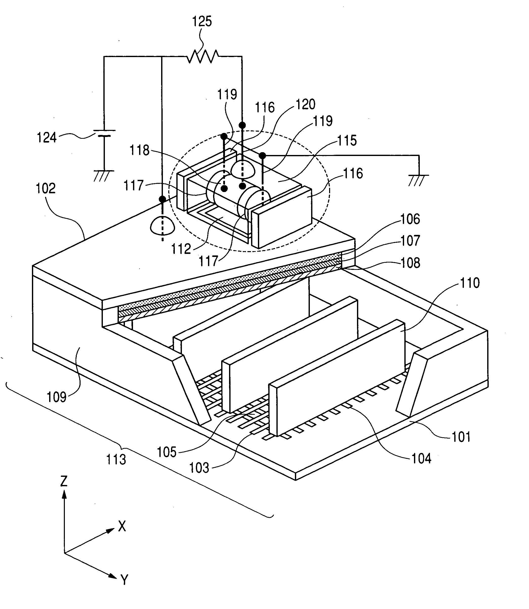
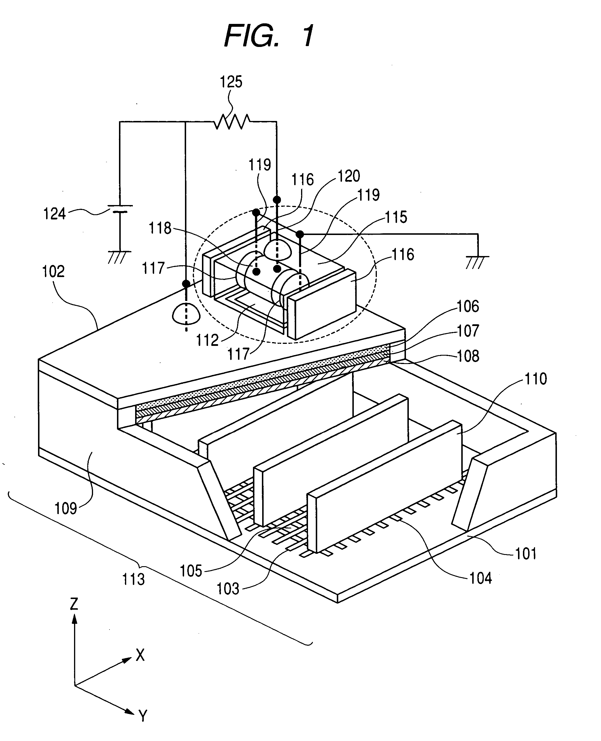
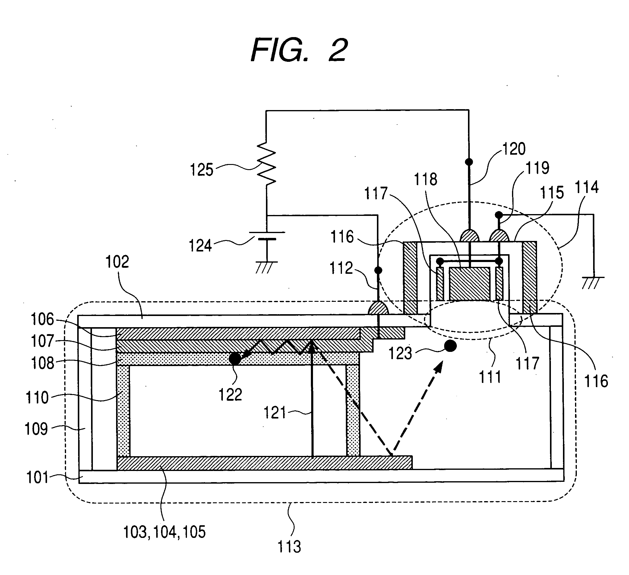
[0058] An image display apparatus of this embodiment has a structure similar to that illustrated in the schematic views of FIGS. 1 and 2. The image display apparatus of this embodiment includes an electron source 105 where a plurality (768 rows×3840 columns) of surface conduction type electron emitting elements form a passive matrix on a substrate. As illustrated in FIG. 1, an ion pump 114 is attached to a face plate outside the image display area, and communicates with the inside of a vacuum container through an opening 111 for the ion pump provided in advance in the face plate. In the ion pump, a cylindrical anode 118 and cathodes 117 provided near plane portions on both sides of the cylinder are placed in a glass case (housing) 115, and magnet plates 116 are in intimate contact with the outside of the glass case so as to be in parallel with the cathodes. The anode and the cathodes are connected to terminals 120 and 119, respectively, which are embedded through the glass case.
[00...
embodiment 2
[0088] This embodiment is a specific example of the second aspect of the present invention. An image display apparatus of this embodiment and a method of manufacturing the same are now described in the following with reference to FIG. 8.
(Processes-a2-a12)
[0089] Processes similar to Processes a1-j1, x1, and k1-11 described in Embodiment 1 were carried out.
(Process-m2 (Packaging and Systematization))
[0090] The vacuum container formed in the above-described processes was equipped with a flexible cable, and at the same time, the ion pump was connected. The ion pump anode terminal 120 was, similarly to the case of the anode terminal 112 of an image display portion, treated with a moisture-resistant and high resistant resin (referred to as potting), and was connected to a high voltage cable. Though a high voltage cable of the image display portion was directly connected to the anode power supply 124, the high voltage cable of the ion pump was connected to the anode power supply 124 ...
embodiment 3
[0092] While the ion pump was attached to the face plate in the above Embodiments 1 and 2, the ion pump may be attached to the rear plate. Such an embodiment is now described with reference to FIG. 9.
(Process-a3 (Glass Substrate, Element Electrode Formation))
[0093] A glass plate having an opening 112 formed therein in advance at a position illustrated in FIG. 5 was used. Cleaning and film formation were carried out in the same way as in the case of Embodiment 1.
(Processes-b3-e3)
[0094] Processes similar to Processes b1-e1 described in Embodiment 1 were carried out.
(Process-x3 (Attachment of Anode Connection Terminal and Ion Pump))
[0095] First, the ion pump was assembled in the same process as that of Embodiment 1. Next, electrodes connected to the anode and the cathode of the ion pump were temporarily fixed by frit glass, and at the same time, as shown in FIG. 9 the glass case 115 of the assembled ion pump was temporarily fixed at the location of the opening for the ion pump...
PUM
 Abstract
Description
Claims
Application Information