Sanitizing face mask

a face mask and sanitizing technology, applied in the field of sanitizing devices, can solve the problems of spreading disease and their efficacy, and achieve the effect of reducing the amount of heat and reducing the excess heat caused by leds

Pending Publication Date: 2022-04-28
SPECTOR DONALD +1
View PDF0 Cites 0 Cited by
  • Summary
  • Abstract
  • Description
  • Claims
  • Application Information

AI Technical Summary

Benefits of technology

[0014]The light can be amplified by parabolic reflectors or mirrors and sealed from light leakage to the skin or eyes. Excessive heat caused by the LEDs is reduced due to the air flow through the tube during inhalation and exhalation. The lungs act as an air pump, thereby replacing the need for a fan by the respiratory system itself. Hence, when proper heat dissipating materials are used, the actual heat only creates a slight elevation in the temperature of the air entering the lungs, which is also desirable for the respiratory system. Therefore, the respiratory system itself absorbs the heat energy of the diodes using the face mask as an extension of the respiratory system while also accomplishing no light contact with the skin or eyes at the same time.
[0015]Multiple LEDs can be placed along the extent of the tube. Heat sinks can be attached to the LEDs to further reduce the amount of heat from the LEDs that is released into the region of the mask. The serpentine shape of the tube with multiple curves ensures that air that is inhaled and exhaled is exposed to radiation for a longer period of time than with the use of a shorter, straight tube. The tube can be removable from the outer shell or can be integrally molded with the outer shell.
[0016]It is believed that this invention will add another layer of protection to masks used for mitigation of disease.

Problems solved by technology

Inhalation can bring such organisms into the person and exhalation can deliver particles containing such organisms to others, thereby spreading disease.
While these masks can be somewhat effective in preventing the virus particles from escaping through the mask, their efficacy is limited due to an imprecise fit and limited filtration. it would be desirable to equip the masks with a way to kill the virus particles so that even those that escape from the mask cannot infect the public.

Method used


Image

  • Sanitizing face mask
  • Sanitizing face mask
  • Sanitizing face mask

Examples


Embodiment Construction

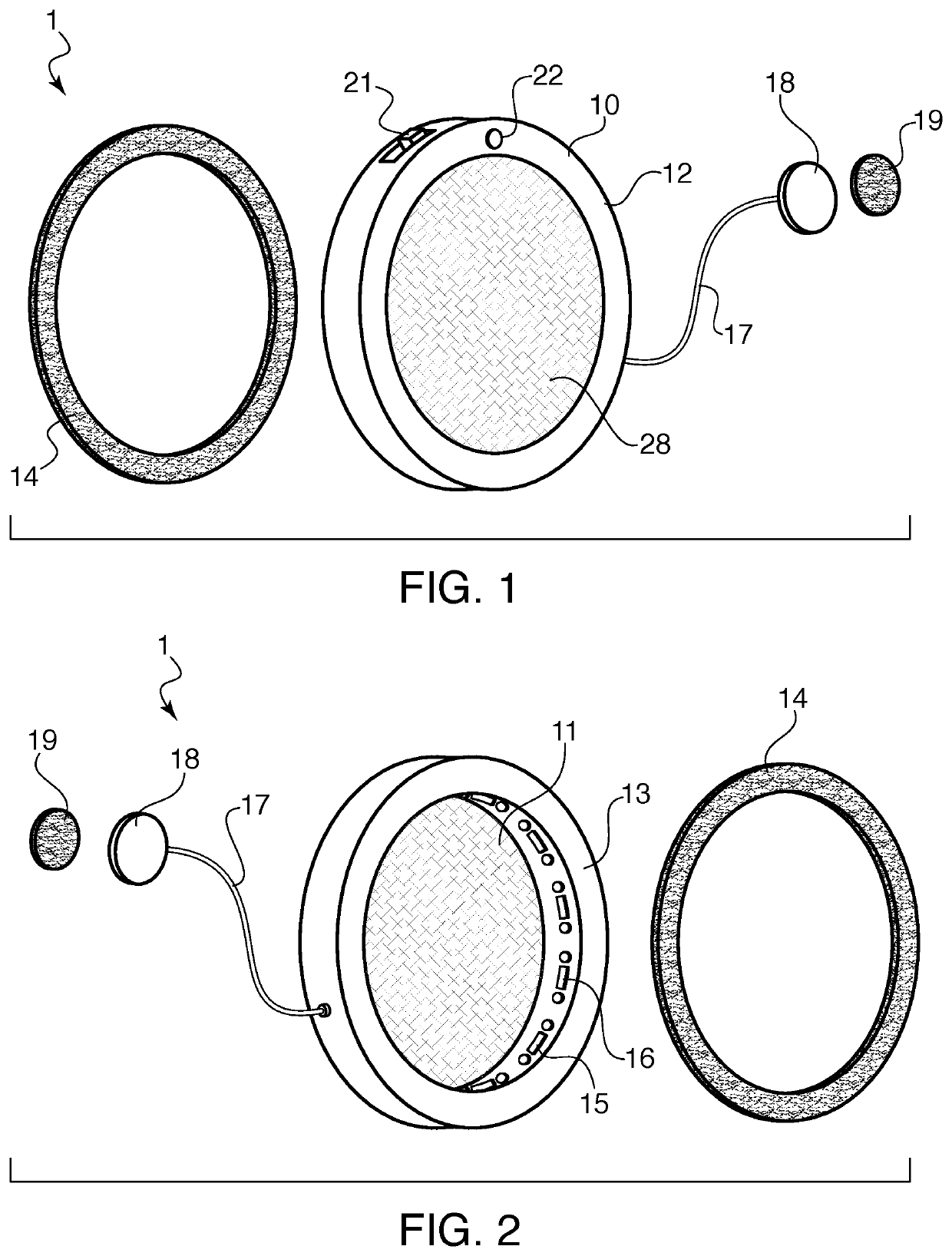
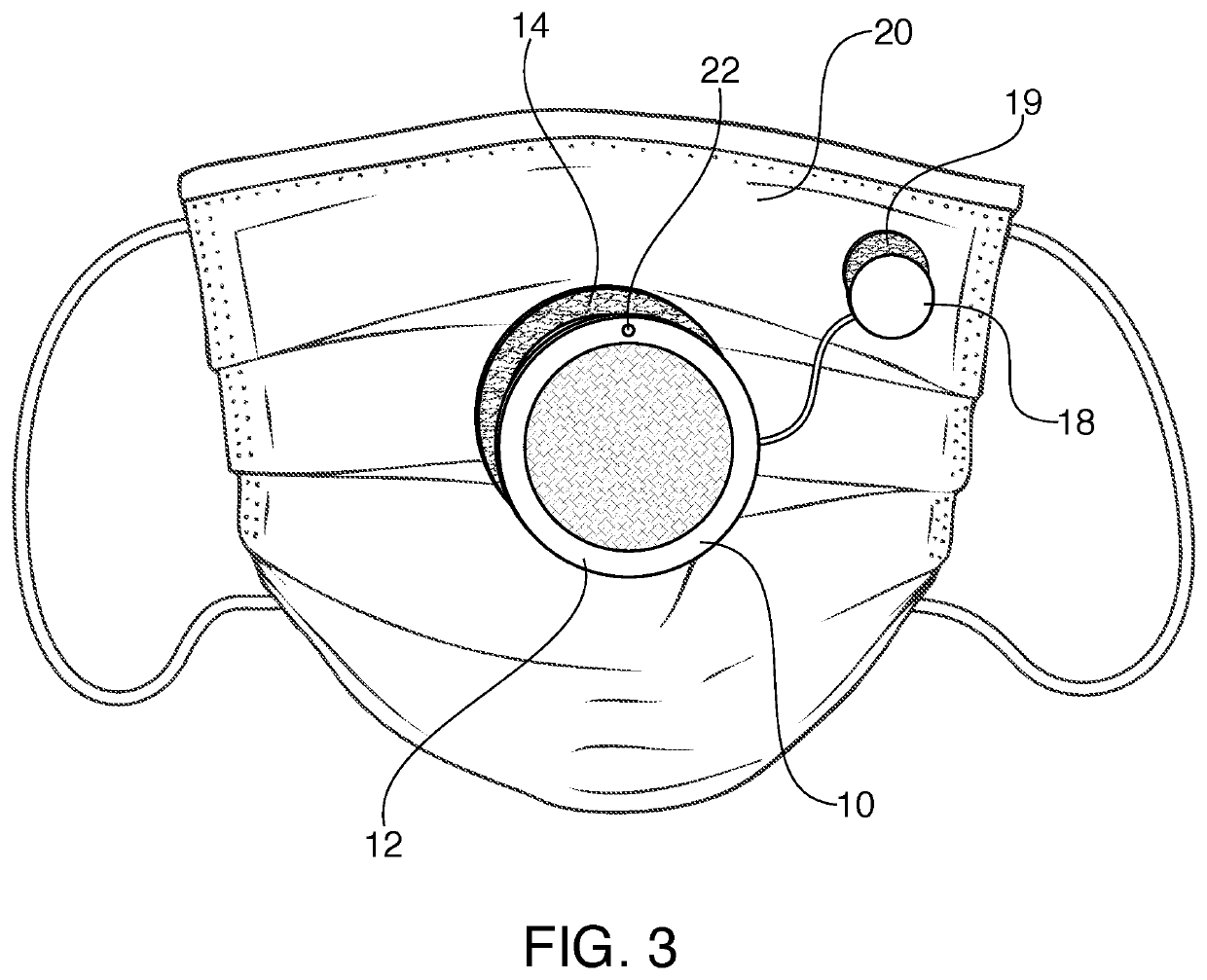
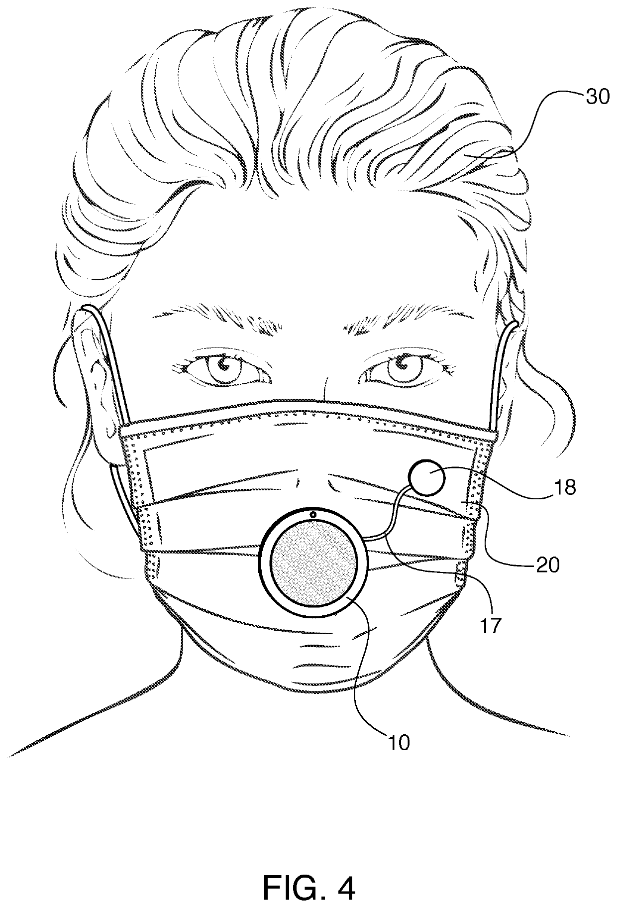
[0031]Referring now in detail to the drawings. FIGS. 1 and 2 show an exploded view of the components of the sanitizing device according to the invention. Sanitizing device 1 is formed from a housing 10 having a central aperture 11, overhanging flanges 12, 13 and an attachment layer 14 that is configured to be adhered to the rear flange 13 and attach the housing 11 to a device such as a face mask 20, as shown in FIG. 13. Housing 11 can be made of any suitable lightweight material, such as plastic or aluminum. Inside housing 11 is a UV LED assembly 15, comprised of individual UV LED's 16, connected by a wire 17′ (shown in FIG. 6). UV assembly 15 is recessed behind flanges 12,13 so that the light emitted therefrom is not directed to the user or to other people facing the user. The number of UV LEDs in the assembly can vary based on the user's preferences, the size of housing and the amount of power that is able to be supplied to the device. A cover layer 28, which can be made of any su...


PUM

PropertyMeasurementUnit
wavelengthaaaaaaaaaa
poweraaaaaaaaaa
shapeaaaaaaaaaa

Abstract

A face mask has an ultraviolet (UV) light-emitting diode (LED) mounted in a respiration tube that extends through an outer shell of the mask. A power source is connected to the UV LED. The respiration tube is serpentine in shape so as to maximize the amount time the air is subjected to the UV radiation. The movement of the air as well as additional heat sinks in the tube reduce the amount of heat radiating from the LEDs during use. This arrangement protects the user and others from excessive UV exposure and heat during use.

Description

CROSS-REFERENCE TO RELATED APPLICATIONS[0001]This application is a continuation-in-part of U.S. patent application Ser. No. 17 / 097,132, filed on Nov. 13, 2020, which claims priority under 35 USC 119(e) of U.S. Provisional Patent Application No. 63 / 105,248, filed on Oct. 24, 2020, the disclosures of both of which are herein incorporated by reference. This application also claims priority under 35 USC 119(e) of U.S. Provisional Application Ser. No. 63 / 196,775, filed on Jun. 4, 2021, the disclosure of which is herein incorporated by reference.BACKGROUND OF THE INVENTION1. Field of the Invention[0002]The present invention relates to a sanitizing device for attachment to a face mask and which utilizes ultraviolet light to sterilize the wearer's exhalations as they are emitted from the mask.2. The Prior Art[0003]The respiratory system represents a closed air system with a self-contained cavity, much smaller than a car cabin, or room. Unlike man-made rooms or vehicles in which air ducts an...

Claims


Application Information

Patent Timeline
Patent Type & Authority Applications(United States)
IPC IPC(8): A61L9/20A62B18/02A41D13/11
CPCA61L9/20A61L2209/12A41D13/11A62B18/025A41D13/1192A62B7/12
Inventor SPECTOR, DONALDPAMINTUAN, LISA
Owner SPECTOR DONALD
Why Eureka
Try Eureka