
Display apparatus and display method

a technology of display apparatus and display method, which is applied in the direction of television system, pulse technique, instruments, etc., can solve the problems of color non-uniformity, inability to improve image quality degradation, and non-uniform luminance, so as to achieve high-level image display without reducing display luminance. , the effect of correcting the non-uniform luminan

Active Publication Date: 2006-03-16
CANON KK
View PDF3 Cites 7 Cited by
  • Summary
  • Abstract
  • Description
  • Claims
  • Application Information

AI Technical Summary

Benefits of technology

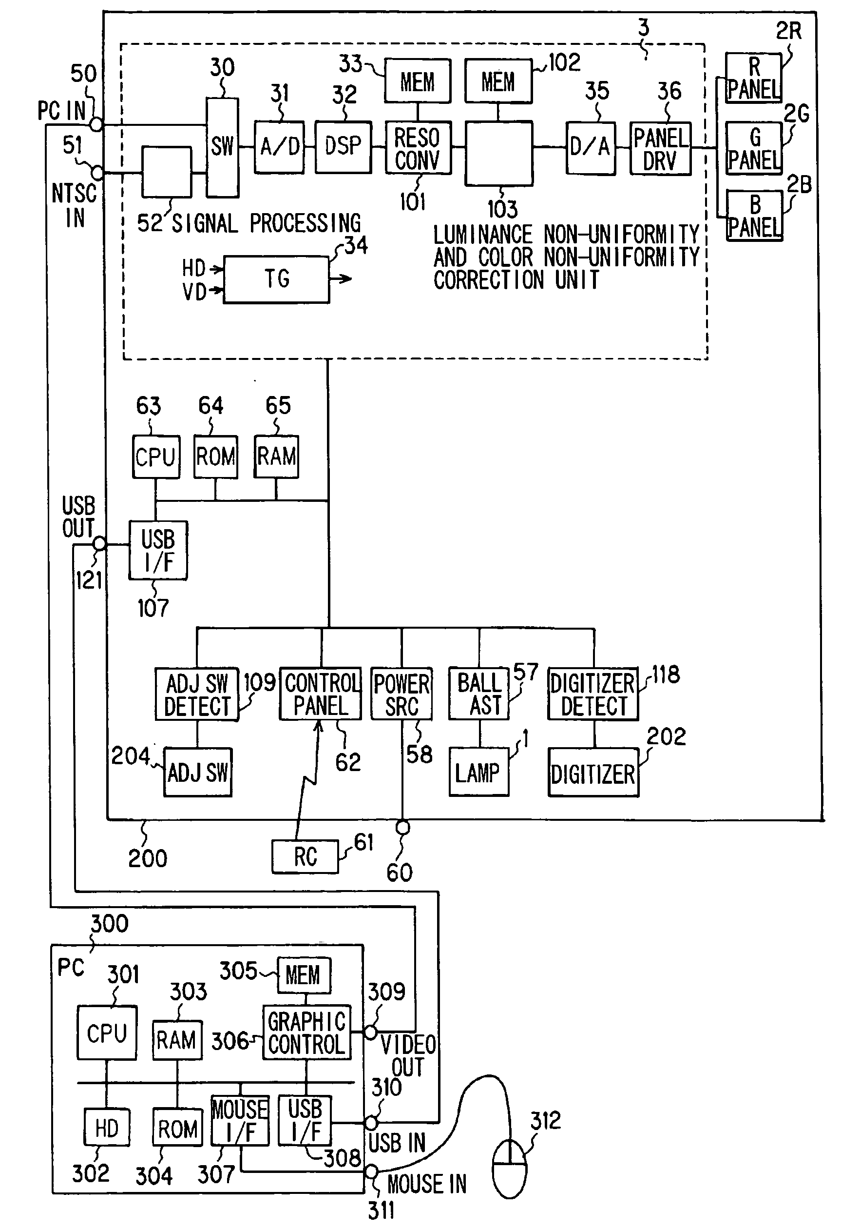
The present invention provides a display apparatus and method that can correct color non-uniformity without reducing the maximum luminance of the display screen. It can also correct both luminance non-uniformity and color non-uniformity when displaying an image at a low luminance with conspicious luminance non-uniformity. The display apparatus includes an optical modulator, an optical system, a luminance non-uniformity correction unit, and a color non-uniformity correction unit. The method involves adjusting a correction coefficient based on the luminance to be displayed and correcting the luminance non-uniformity and color non-uniformity by adjusting the luminance balance among the monochromatic images. The invention allows for high level image display without reducing display luminance.

Problems solved by technology

However, at the high luminance, it is true that the luminance non-uniformity is less conspicuous but the color non-uniformity is still conspicuous.
HEI9-200571, it is impossible to improve image quality degradation resulting from the color non-uniformity.
Demand for reducing the color non-uniformity and the luminance non-uniformity also rises following an increase in a size of the display screen.
As stated above, it is conventionally difficult to realize both an increase in the luminance of the display screen and a reduction in the color non-uniformity and the luminance non-uniformity.

Method used


Image

  • Display apparatus and display method
  • Display apparatus and display method
  • Display apparatus and display method

Examples


Embodiment Construction

[0025] Most preferred embodiment of the present invention will be described hereinafter in detail with reference to the drawings. It should be noted, however, that sizes, materials, shapes, functions, relative positions, etc. of constituent elements described in the embodiment are not intended to limit the scope of the present invention unless specified otherwise.

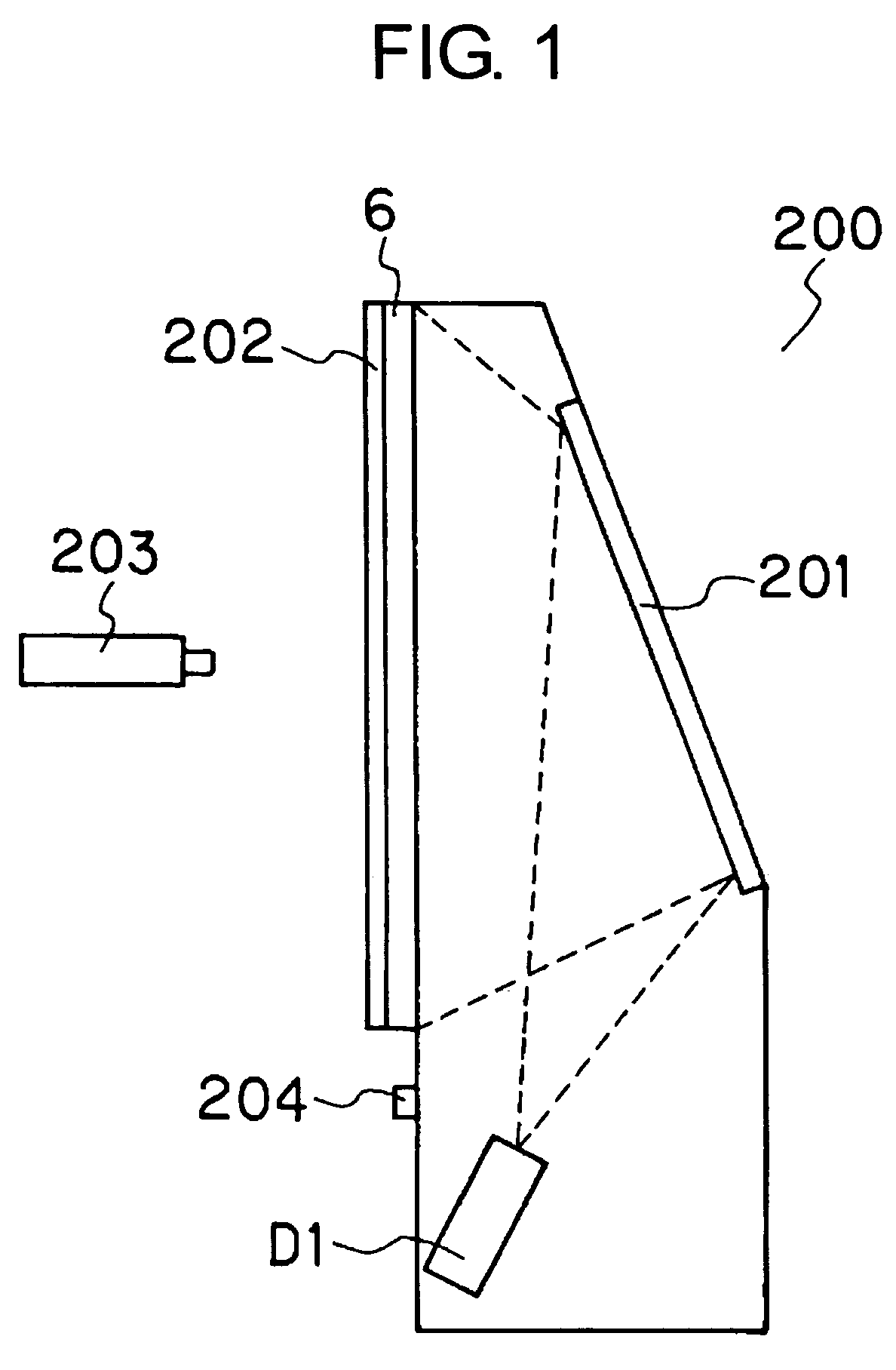
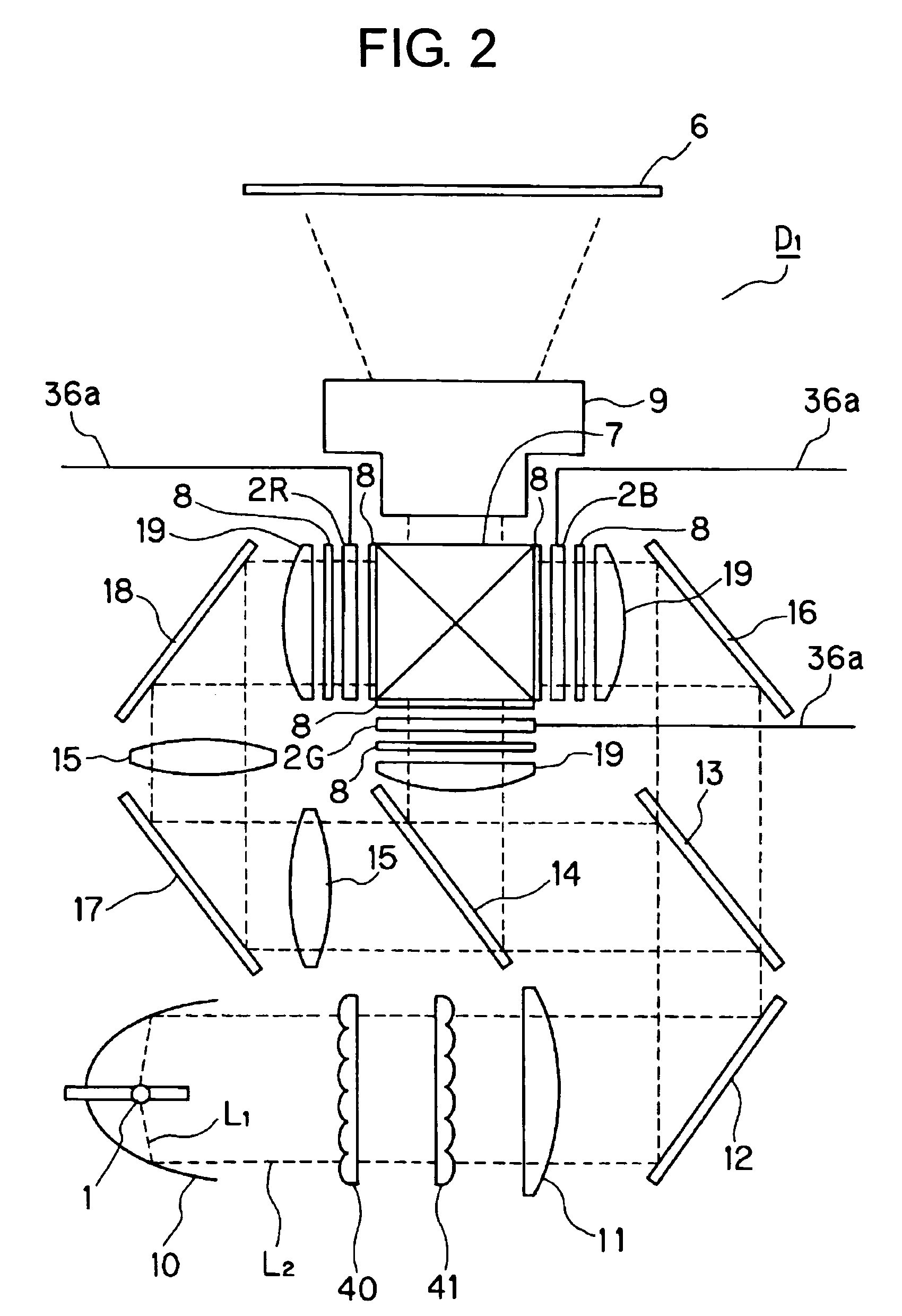
[0026]FIG. 1 is a side sectional view of a rear projection display apparatus 200 according to an embodiment of the present invention. Referring to FIG. 1, an image projected from a projection display engine D1 is reflected by a reflection mirror 201 and projected on a rear surface of a screen 6. A digitizer 202 is attached to a front surface of the screen 6. The digitizer 202 inputs position coordinates input from the front surface of the screen 6 using a digitizer pen 203 to the display apparatus 200. As the digitizer 202, any one of an optical digitizer, a pressure-sensitive digitizer, an ultrasonic digitizer and the lik...


PUM


Abstract

A display apparatus includes a plurality of optical modulators that display monochromatic images, respectively, an optical system that synthesizes the monochromatic images into a color image, a luminance non-uniformity correction unit that adjusts a correction coefficient according to a luminance to be displayed, and that corrects a luminance non-uniformity in the monochromatic image using the adjusted correction coefficient, and a color non-uniformity correction unit that adjusts a luminance balance among the monochromatic images per pixel or pixel block, thereby correcting a color non-uniformity in the color image.

Description

BACKGROUND OF THE INVENTION [0001] 1. Field of the Invention [0002] The present invention relates to a display apparatus and a display method thereof. More specifically, the present invention relates to a method for improving color non-uniformity and luminance non-uniformity. [0003] 2. Description of the Related Art [0004] As methods for correcting color non-uniformity of a display apparatus, there is known a method, as disclosed in, for example, Japanese Patent Application Laid-Open (JP-A) No. HEI10-84551 (Japanese Patent No. 3202613), for correcting the color non-uniformity by dividing a display screen into blocks, making the divided blocks uniform in luminance level, and thereby correcting the color non-uniformity that occurs to the display screen. [0005] There is also known a method, as disclosed in JP-A No. HEI9-200571, for increasing a correction amount large at a low luminance compared to at a high luminance at which the input video signal level is high, using a gain adjustme...

Claims


Application Information

Patent Timeline
Patent Type & Authority Applications(United States)
IPC IPC(8): H04N5/52
CPCH04N9/3182H04N5/74
Inventor SAKASHITA, YUKIHIKO
Owner CANON KK
Learn More