Pixel circuit, display apparatus and electronic apparatus equipped with current driving type light-emitting device

Inactive Publication Date: 2008-04-22
SEIKO EPSON CORP
View PDF69 Cites 56 Cited by
  • Summary
  • Abstract
  • Description
  • Claims
  • Application Information

AI Technical Summary

Benefits of technology

[0132]By virtue of the use of the display apparatuses of the invention, reduction in the display luminance and screen irregularities attributable to deterioration over time and variations in characteris

Problems solved by technology

However, for a current driving type light-emitting device such as an organic EL device, a driving current flows through the inside of the device, so that deterioration over time occurs irrespective of scale.
For example, with respect to the organic EL device, it has been reported that significant deterioration over time occurs.
Additionally, the degree of deterioration over time varies among each organic EL device.
Further, for a TFT-OELD, the TFT deteriorates over time because of a current flowing through the TFT as a driving device.
For this reason, in a display apparatus employing the TFT-OELD, a problem of deterioration in image quality arises when the organic EL device or the driving TFT deteriorates over time.
That is, deterioration in current decrease or a quantity of emitted light decrease leads to degradation of screen luminance, while variation in these decreases cause screen irregularities.
Especially, these kinds of deterioration occur depending upon luminescence characteristics of the organic EL device during manufacture, variations in c

Method used


Image

  • Pixel circuit, display apparatus and electronic apparatus equipped with current driving type light-emitting device
  • Pixel circuit, display apparatus and electronic apparatus equipped with current driving type light-emitting device
  • Pixel circuit, display apparatus and electronic apparatus equipped with current driving type light-emitting device

Examples


first embodiment

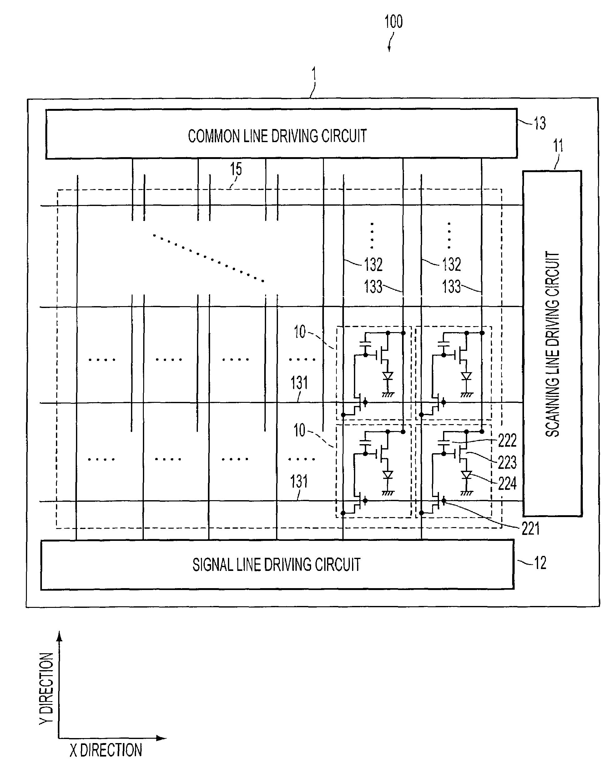
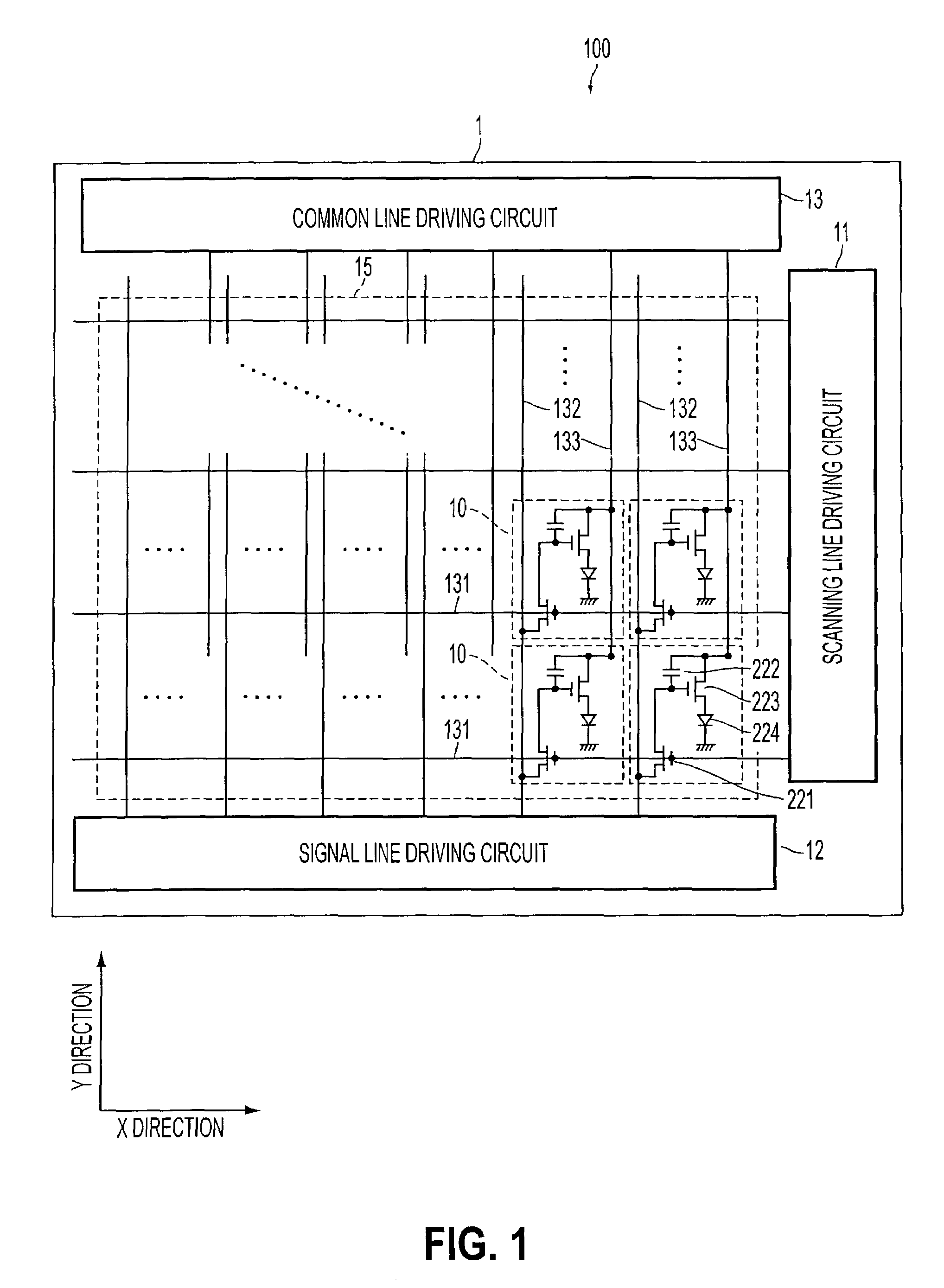
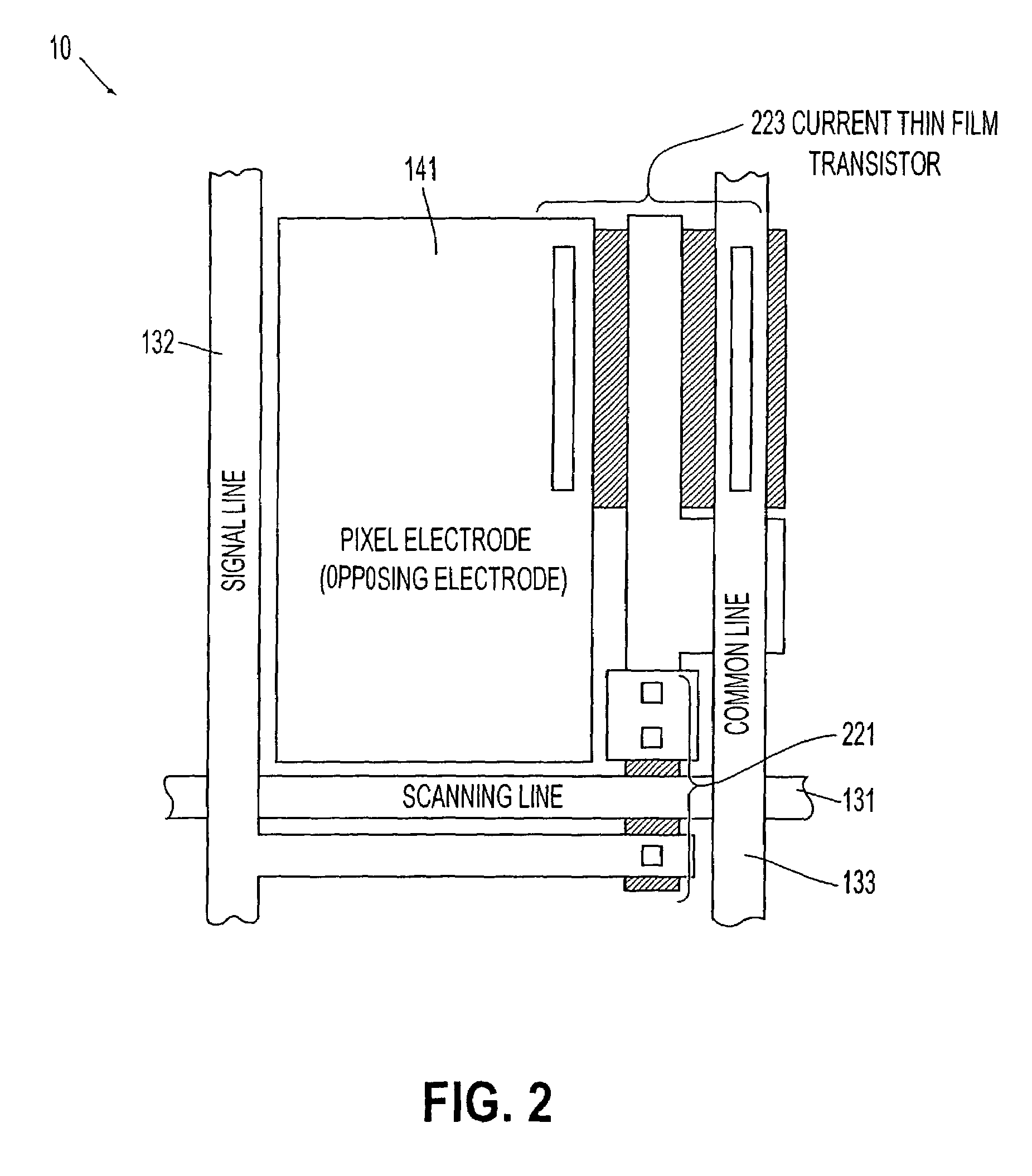
[0165]FIG. 3 is a block diagram of a display apparatus provided with a TFT-OELD according to a first embodiment of the present invention. In the present embodiment, the common electrode driving circuit 13 supplies a power source signal of a predetermined potential (for example, a positive potential) to the common line 133 (refer to FIGS. 1 and 2). The opposing electrode driving circuit 14 supplies a power source signal of a predetermined voltage (for example, a ground potential) to an opposing electrode arranged opposite to the pixel electrode 141 (refer to FIG. 2) with the organic EL device 224 sandwiched therebetween.

[0166]In the present embodiment, to especially correct a decrease in the driving current resulting from deterioration over time of the organic EL device 224 or the current TFT 223 (accordingly a decrease in a quantity of emitted light of the organic EL device 224), a current measuring equipment 16, a comparison circuit 21a, a voltage control circuit 22a, and a control...

second embodiment

[0183]FIG. 8 is a block diagram of a display apparatus equipped with a TFT-OELD according to the second embodiment of the present invention. In FIG. 8, the same components indicated in FIG. 3 as in the first embodiment are assigned the same reference symbols, and a description thereof is omitted.

[0184]In the present embodiment, a voltage between the common electrode and the opposing electrode is applied to a monitoring organic EL device 17a in a current monitoring region 17 equipped adjacent to the display region 15, and the monitoring organic EL device 17 is current-driven at a display period under almost the same conditions as for the display organic EL device 224 (refer to FIG. 1). Then, in performing a correction processing for deterioration over time, the current measuring equipment 16 measures a current Idm flowing through the monitoring organic EL device 17a. The output voltage (Vcom) of the common electrode driving circuit 13 is controlled by the comparison circuit 21a, the ...

third embodiment

[0188]FIG. 9 is a block diagram of a display apparatus equipped with a TFT-OELD according to a third embodiment of the present invention. In FIG. 9, the same components indicated in FIG. 3 as in the first embodiment are assigned the same reference symbols and a description thereof is omitted.

[0189]In the present embodiment, in place of the current measuring equipment 16 in the first embodiment, a quantity-of-emitted-light measuring equipment 18 is provided to measure a quantity of emitted light of the displaying organic EL device 224 (refer to FIG. 1) in the display region 15. In correcting deterioration over time, the scanning signal of a predetermined voltage from the scanning line driving circuit 11, the data signal of a predetermined voltage from the signal line driving circuit 12, and the power source signal of a predetermined voltage from the common electrode driving circuit 13 and the opposing electrode driving circuit 14 are applied. The quantity-of-emitted-light measuring e...


PUM


Abstract

A display apparatus is provided with a current driving type light-emitting device and a driving device for controlling a driving current flowing through the light-emitting device for each pixel of the display apparatus. The display apparatus consists of power source units for supplying power for causing a driving current to flow via the driving device to the light-emitting device via a power source wire, and signal wire driving units for supplying a data signal to the driving device via signal wires. In addition, voltage adjusting units adjust a voltage for the power source units or a data signal from the signal wire driving units so that a quantity of a driving current flowing through the light-emitting device when a data signal of a predetermined voltage is supplied to the driving device via signal wires or a quantity of emitted light emitted from the light-emitting device comes close to a predetermined reference value.

Description

[0001]This is a Division of application Ser. No. 09 / 171,526 filed Oct. 21, 1998 now U.S. Pat. No. 6,518,962, which in turn is a National Stage of PCT / JP98 / 00971 filed Mar. 6, 1998. The entire disclosure of the prior application(s) is hereby incorporated by reference herein in its entirety.BACKGROUND OF THE INVENTION[0002]1. Field of the Invention[0003]The present invention relates to a pixel circuit which has a current driving type light-emitting device such as an organic electroluminescent device (hereinafter, called “organic EL device”) and a driving device such as a thin film transistor for driving the current driving type light-emitting device. The present invention also relates to a display apparatus having pixels, each pixel being provided with such a pixel circuit, and further to an electronic apparatus having the same. In particular, the present invention concerns a driving circuit, as well as a display apparatus, capable of compensating for deterioration with time of the cu...

Claims


Application Information

Patent Timeline
IPC IPC(8): G09G5/00G09G3/30G09G3/32G09G3/36H01L27/32H05B44/00
CPCG09G3/3233H01L27/3269H05B33/08G09G3/32G09G2300/0417G09G2300/0819G09G2300/0842G09G2300/088G09G2320/029G09G2320/043G09G2320/045G09G2330/02G09G2330/028G09G2360/145G09G2360/148H01L27/3262G09G2320/0285H05B45/00H05B44/00H10K59/1213H10K59/13
Inventor KIMURA, MUTSUMISHIMODA, TATSUYAKIGUCHI, HIROSHI
Owner SEIKO EPSON CORP
Why Eureka
Try Eureka