Liquid crystal display device

a liquid crystal display and display device technology, applied in bridge construction, instruments, bridges, etc., can solve the problem of large viewing angle dependence of tn lcd, and achieve the effect of suppressing the improvement of moving image display performance and reducing display luminan

Inactive Publication Date: 2005-09-08
SHARP KK
View PDF12 Cites 3 Cited by
  • Summary
  • Abstract
  • Description
  • Claims
  • Application Information

AI Technical Summary

Benefits of technology

[0024] According to the present invention, an alignment-divided vertical alignment LCD that can present high-definition moving image display when OS driving is adopted is provided. In addition, in the alignment-divided vertical alignment LCD of the present invention, reduction in display luminance that may result from the improvement in moving image display performance can be suppressed. The LCD of the present invention is suitably usable as an LCD TV by being provided with a circuit for receiving television broadcast. Also, the LCD of the present invention is suitably applicable to electronic equipment used for display of moving images, such as personal computers and PDAs.

Problems solved by technology

The TN LCD however has a problem of being large in viewing angle dependence that results from the alignment of liquid crystal molecules.
However, as a result of examinations done by the inventors of the present invention, it has been found that a new problem arises when the OS driving is adopted for alignment-divided vertical alignment LCDs such as the MVA LCD described above.

Method used


Image

  • Liquid crystal display device
  • Liquid crystal display device
  • Liquid crystal display device

Examples


Embodiment Construction

[0043] Hereinafter, LCDs of embodiments of the present invention and driving methods for the LCDs will be described with reference to the relevant drawings.

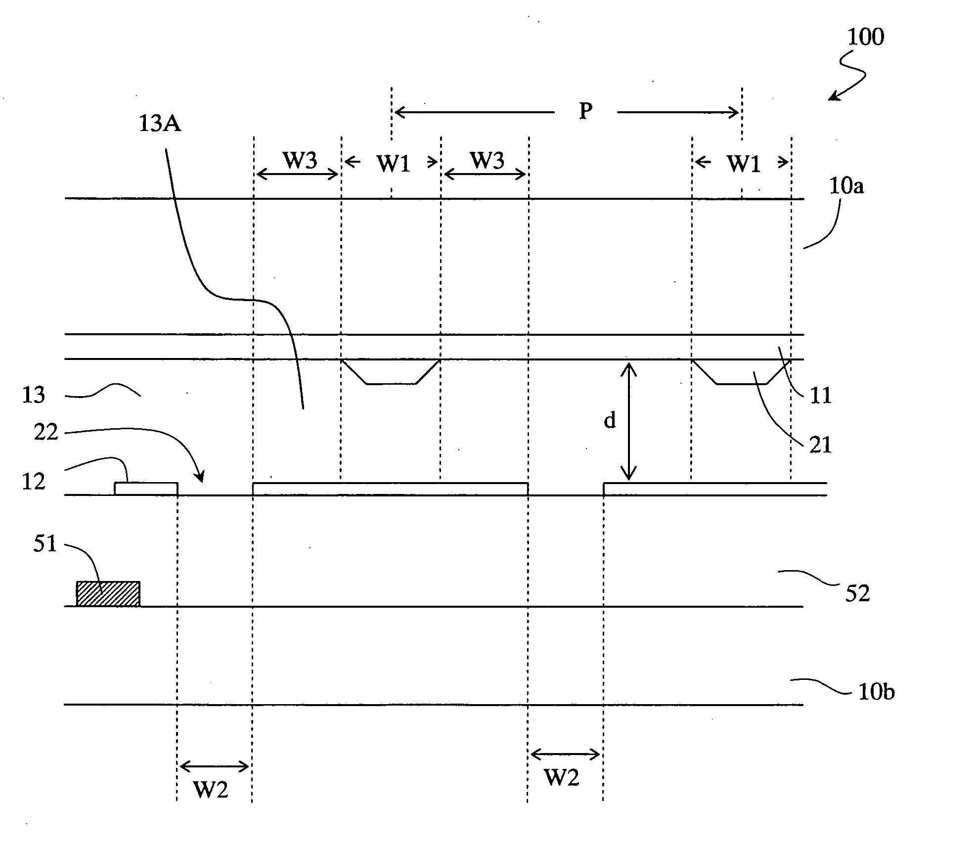
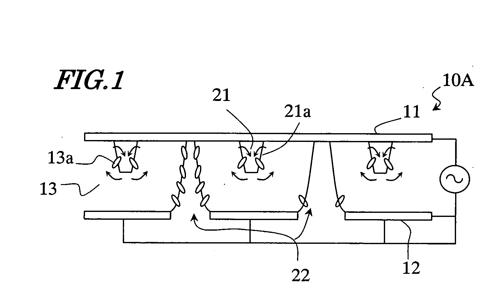
[0044] First, a basic configuration of an alignment-divided vertical alignment LCD of an embodiment of the present invention will be described with reference to FIG. 1. The alignment-divided vertical alignment LCD exemplified herein is an MVA LCD having stripe-shaped ribs and stripe-shaped slits.

[0045] The LCD of an embodiment of the present invention includes a plurality of pixels each having a first electrode 11, a second electrode 12 facing the first electrode 11, and a vertically aligned liquid crystal layer 13 placed between the first electrode 11 and the second electrode 12. The vertically aligned liquid crystal layer 13 includes liquid crystal molecules having negative dielectric anisotropy that are aligned roughly vertically (for example, at an angle in the range between 87° and 90°) with respect to the plane of the fir...


PUM

PropertyMeasurementUnit
widthaaaaaaaaaa
widthaaaaaaaaaa
widthaaaaaaaaaa

Abstract

The liquid crystal display device of the invention has a plurality of pixels each having a first electrode, a second electrode facing the first electrode, and a vertically aligned liquid crystal layer placed between the first and second electrodes. The device includes: ribs in a stripe shape having a first width placed in the first electrode side of the liquid crystal layer; slits in a stripe shape having a second width placed in the second electrode side of the liquid crystal layer; and liquid crystal regions having a third width defined between the ribs and the slits. The third width is in a range between 2 μm and 14 μm, and the ratio of the third width to the second width is in a range between 1.0 and less than 1.5.

Description

BACKGROUND OF THE INVENTION [0001] 1. Field of the Invention [0002] The present invention relates to a liquid crystal display device and a driving method for the same, and more particularly relates to a liquid crystal display device suitably used for display of moving images and a driving method for the same. [0003] 2. Description of the Related Art [0004] In recent years, liquid crystal display devices (LCDs) have increasingly come into widespread use. Among various types of LCDs, mainstream has been a TN LCD in which a nematic liquid crystal material having positive dielectric anisotropy is twisted. The TN LCD however has a problem of being large in viewing angle dependence that results from the alignment of liquid crystal molecules. [0005] To improve the viewing angle dependence, alignment-divided vertical alignment LCDs have been developed, and use of these LCDs is expanding. For example, Japanese Patent Gazette No. 2947350 (Literature 1) discloses an MVA LCD as one of the align...

Claims


Application Information

Patent Timeline
Patent Type & Authority Applications(United States)
IPC IPC(8): G02F1/133G02F1/1337G02F1/1335G02F1/1343G09G3/36
CPCG02F1/134336G02F1/133707E01D21/00E01D19/02E01D19/04
Inventor KUBO, MASUMIYAMAMOTO, AKIHIROOHGAMI, HIROYUKIOCHI, TAKASHIYOKOYAMA, RYUICHI
Owner SHARP KK
Why Eureka
Try Eureka