Supercharge Your Innovation With Domain-Expert AI Agents!

Vehicle headlamp

a technology for headlamps and vehicles, applied in the direction of lighting and heating devices, transportation and packaging, lighting support devices, etc., can solve the problems of glare caused to the drivers of oncoming vehicles, and achieve the effect of improving long distance visibility and preventing glar

Inactive Publication Date: 2006-03-16
KOITO MFG CO LTD
View PDF4 Cites 9 Cited by
  • Summary
  • Abstract
  • Description
  • Claims
  • Application Information

AI Technical Summary

Benefits of technology

The present invention provides a projector-type vehicle headlamp equipped with a movable shade that prevents glare to drivers of oncoming vehicles even when the vehicle pitches while traveling under low-beam illumination conditions. The headlamp forms a low beam light distribution pattern with a cutoff line where the oncoming lane side section is formed as a horizontal cutoff line. The light-gathering reflection surface is formed on a reflection area contributing to the formation of the horizontal cutoff line. The movable shade is positioned between the light source and the reflection surface and can be moved between a light shielding position and a light shielding alleviating position. The actuator moves the movable shade between the light shielding position and the light shielding alleviating position. The headlamp is designed to improve visibility and long-distance visibility.

Problems solved by technology

As a result, when the vehicle is pitching, a glare is caused to the drivers of oncoming vehicles.

Method used


Image

  • Vehicle headlamp
  • Vehicle headlamp
  • Vehicle headlamp

Examples


Embodiment Construction

[0038] Embodiments of the invention will be described with reference to the accompanying drawings.

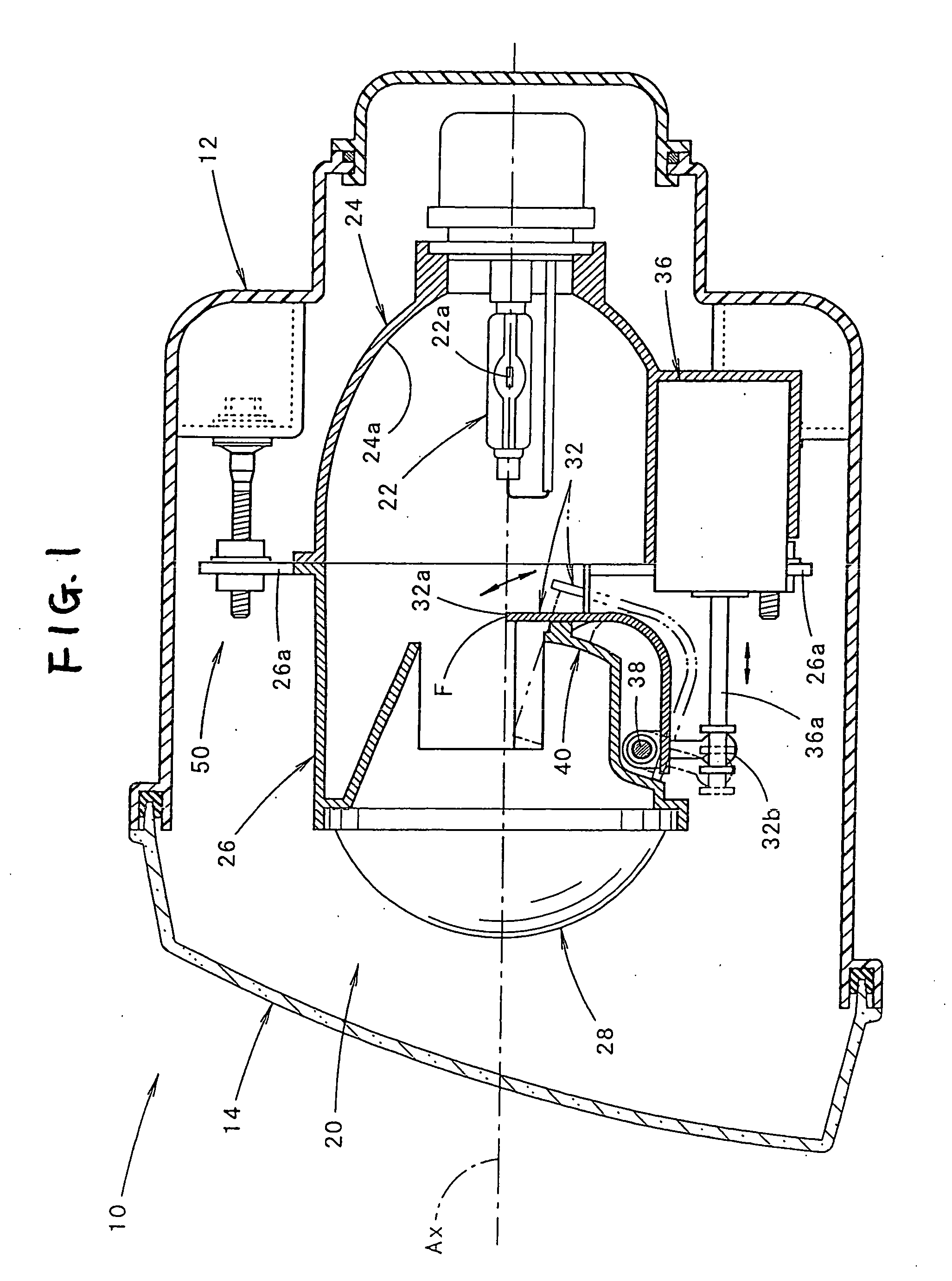
[0039]FIG. 1 shows a side cross section of a vehicle headlamp 10 according to an embodiment of the present invention.

[0040] As shown in FIG. 1, the vehicle headlamp 1 comprises a lamp room formed by a lamp body and a see-through translucent cover 14 attached to the front end opening thereof, the lamp room accommodating a lighting fixture unit 20 having an optical axis Ax extending in the longitudinal direction of a vehicle via an aiming mechanism 50 in a tiltable fashion in vertical and horizontal directions.

[0041] Once aiming adjustment is made by the aiming mechanism 50, the optical axis Ax of the lighting fixture unit 20 of the vehicle headlamp 10 extends in a direction 0.5 to 0.6 degrees downward with respect to the longitudinal direction of the vehicle.

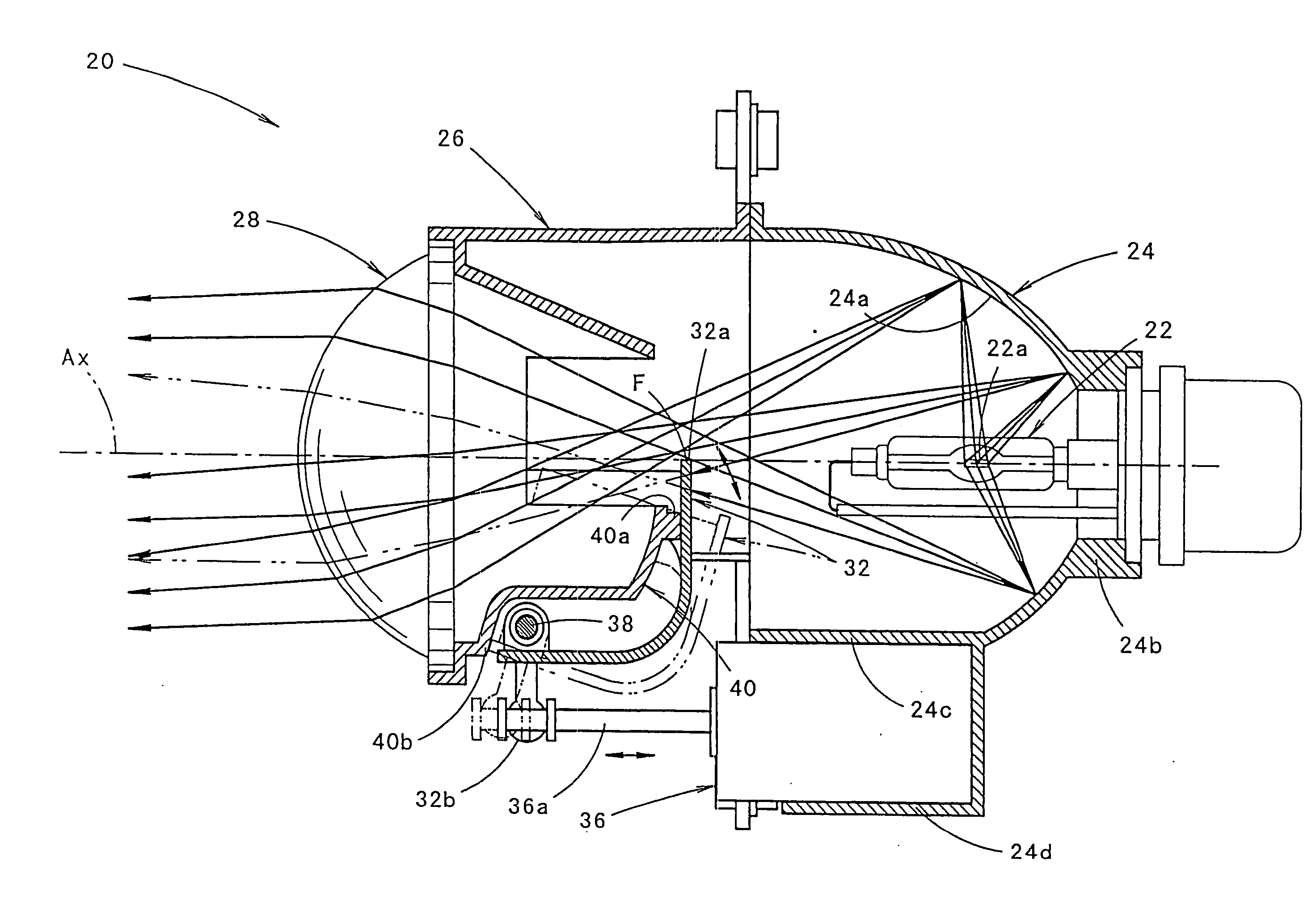
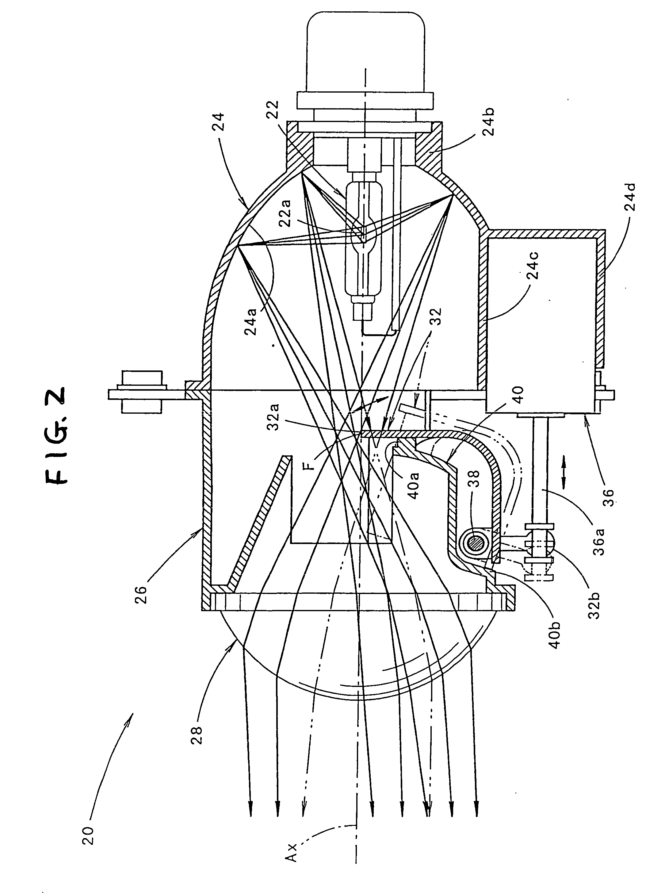
[0042]FIGS. 2 and 3 show a side cross section and a horizontal cross section of the lighting fixture unit 20 as a standalone un...


PUM


Abstract

A light-gathering reflection surface is provided on a part of a reflection area on a reflection surface of the reflector. Light from the light source reflected onto the light-gathering surface is emitted as light substantially parallel to an optical axis from the projection lens in the front direction of a lighting fixture. Thus, an irradiation amount on a vicinity of a horizontal cutoff line is reduced, and a center intensity in a front direction in a high beam light distribution pattern is enhanced.

Description

[0001] The present application claims foreign priority based on Japanese Patent Application No. P.2004-264036, filed on Sep. 10, 2004, the contents of which are incorporated herein by reference. BACKGROUND OF THE INVENTION [0002] 1. Field of the Invention [0003] The present invention relates to a projector-type vehicle headlamp, and in particular to a vehicle headlamp having a movable shade. [0004] 2. Related Art [0005] There is a projector-type vehicle headlamp having a projection lens arranged on an optical axis extending in a longitudinal direction of a vehicle and a light source arranged behind a rear focus of a projection lens. The projector-type vehicle headlamp is designed to reflect light from the light source onto an area close to the optical axis. When a low beam light distribution pattern is formed, a shade arranged so as to position its top end edge near the optical axis in a vicinity of the rear focus of the projection lens is used to shield a part of a reflected light ...

Claims


Application Information

Patent Timeline
Patent Type & Authority Applications(United States)
IPC IPC(8): F21V17/02F21Y101/00
CPCF21S48/1186F21S48/1778F21S48/1358F21S41/172F21S41/334F21S41/689
Inventor YAGI, TAKAYUKIUCHIDA, NAOKI
Owner KOITO MFG CO LTD
Features
  • R&D
  • Intellectual Property
  • Life Sciences
  • Materials
  • Tech Scout
  • Unparalleled Data Quality
  • Higher Quality Content
  • 60% Fewer Hallucinations
Learn More