Lancet and needle insertion device

Inactive Publication Date: 2006-03-16
ARKRAY INC
View PDF16 Cites 88 Cited by
  • Summary
  • Abstract
  • Description
  • Claims
  • Application Information

AI Technical Summary

Benefits of technology

[0006] An object of the present invention is to enhance the

Problems solved by technology

Therefore, it is not safe in a sense that there is a considerable possibility that the user is hurt by the needle tip.
In addition, it is troublesome for the use

Method used


Image

  • Lancet and needle insertion device
  • Lancet and needle insertion device
  • Lancet and needle insertion device

Examples


Embodiment Construction

[0042] Preferred embodiments of the present invention will be described below in detail with reference to the accompanying drawings.

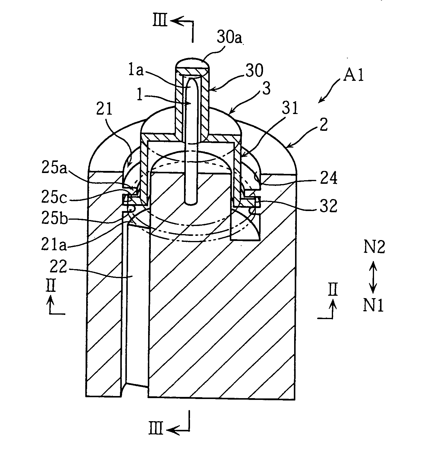
[0043] First, a first embodiment of the present invention will be described with reference to FIGS. 1 through 8.

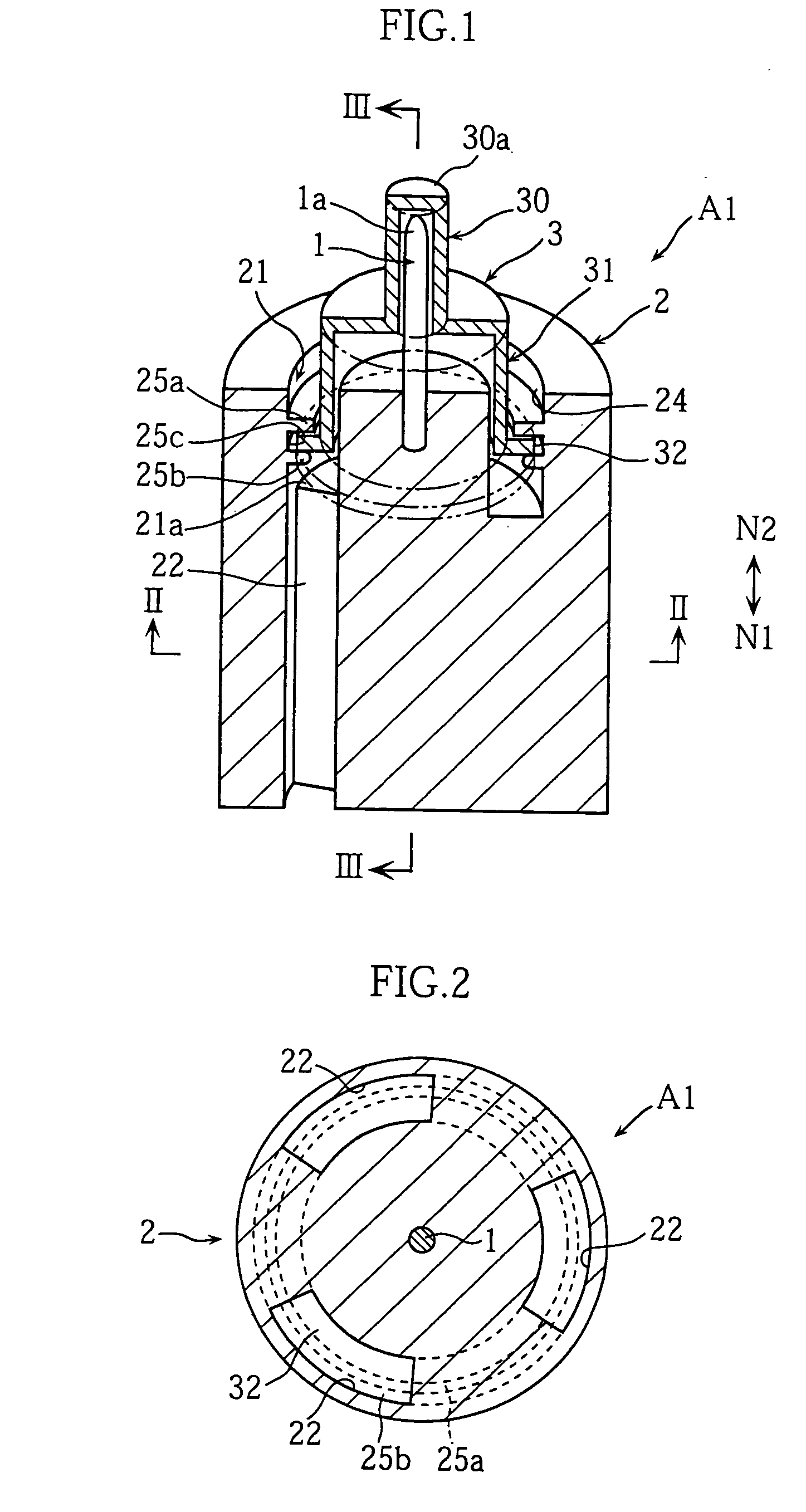
[0044] As shown in FIGS. 1 through 3A, the lancet A1 includes a lancet body 2 having a lancing needle 1, and a cap 3 for accommodating the lancing needle 1.

[0045] The lancet body 2 is formed with an annular hole 21 and three through-holes 22.

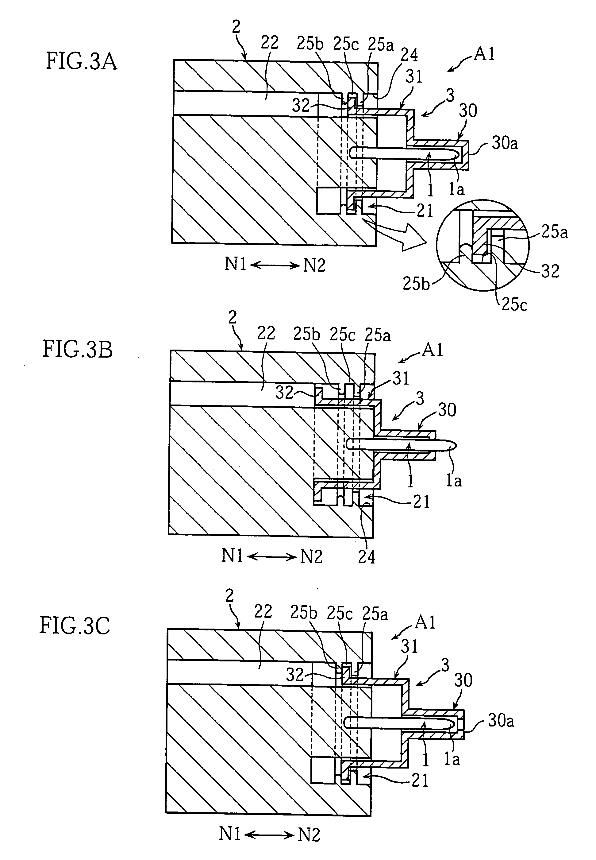
[0046] As better shown in FIGS. 3A and 3B, the annular hole 21 serves to receive an end of the cap 3 while allowing the movement of the cap 3 relative to the lancet body 2. As shown in FIGS. 1 through 3A, the hole 21 has an inner surface 24 formed with a first and a second annular projections 25a and 25b projecting radially inward. The amount of projection of the first annular projection 25a is greater than that of the second annular projection 25b. When the cap 3 is moved relative to the lancet body 2...


PUM


Abstract

The present invention relates to a lancet (A1) in which a first member (2) including a lancing element (1) and a second member (3) for accommodating the tip (1a) of the lancing element (1) are arranged movably relative to each other. In the lancet (A1), when a load greater than a predetermined value is applied in a direction to make the first and the second members (2, 3) approach each other, the tip (1a) of the lancing element (1) is capable of projecting from the second member (3) by relative movement between the first member (2) and the second member (3) in a direction to approach each other. The tip (1a) of the lancing element (1) can be accommodated in the second member (3) so as not to project from the second member (3) by relative movement between the first member (2) and the second member (3) in a direction to separate from each other.

Description

TECHNICAL FIELD [0001] The present invention relates to a technique for drawing body fluid from the skin to measure e.g., the concentration of a test substance contained in the body fluid. BACKGROUND ART [0002] Referring to FIG. 18 of the present application, an example of a conventional lancet (see e.g., JP-A-H08-597) comprises a lancet body 100 provided with a needle 101 and a screw portion 104, and a cap 110 is attached to the body in a manner such that it can be moved in a N1-N2 direction shown in the figures. [0003] The cap 110 is made hollow to accommodate the needle tip 101a of the needle 101. The cap 110 includes a cover member 111 and a needle tip protection head 113 formed integral with the cover member 111. Between the cover member 111 and the needle tip protection head 113 is provided a constricted portion 114, so that the needle tip protection head 113 can be separated from the cover member 111 to expose the needle tip 101a of the needle 101. The cover member 111 has an...

Claims


Application Information

Patent Timeline
IPC IPC(8): A61B17/32A61B5/15
CPCA61B5/1411A61B5/150022A61B5/150435A61B5/150572A61B5/150587A61B5/150603A61B5/150633A61B5/150702A61B5/1513A61B5/15186
Inventor SAKATA, TETSUYA
Owner ARKRAY INC
Why Eureka
Try Eureka