Vascular sealing device with locking system

a sealing device and locking system technology, applied in the field of medical devices, can solve the problems of difficult manufacturing of sealing devices with slipknots, and achieve the effect of facilitating the one-way locking movement of the locking apparatus

Inactive Publication Date: 2006-03-16
KENSEY NASH HLDG
View PDF100 Cites 200 Cited by
  • Summary
  • Abstract
  • Description
  • Claims
  • Application Information

AI Technical Summary

Benefits of technology

[0008] According to some embodiments, the first suture passageway is substantially linear and tapered from a first end nearest the anchor to a second end farthest from the anchor. The first suture passageway may therefore be conical. The first end of the first suture passageway has diameter larger than an outer diameter of the suture, and the second end of the first suture passageway has a diameter smaller than the outer diameter of the suture. Therefore, the suture is radially compressed as it passes through the first suture passageway in a first direction from the larger to the smaller diameter. The compressing of the suture prevents the suture from retracting through the first suture passageway.
[0011] Another embodiment of the invention provides a tissue puncture closure device for partial insertion into and sealing of an internal tissue wall puncture. The tissue puncture closure device comprises a filament, an anchor for insertion through the tissue wall puncture attached to the filament at a first end of the closure device, a sealing plug disposed proximal of the anchor, and a locking apparatus arranged adjacent to the sealing plug for compressing the sealing plug toward the anchor. The filament is threaded through the locking apparatus and the locking apparatus is movable along the filament toward the sealing plug, but is not movable along the filament away from the sealing plug. A wedge, snare, taper, or one or more cantilevered levers may facilitate the one-way locking movement of the locking apparatus. The tissue puncture closing device may also include a tube slidingly disposed about the filament proximal to the locking apparatus for advancing the locking apparatus along the filament.

Problems solved by technology

However, prior to a successful deployment of the sealing plug or another vascular tool, the introducer must be properly located within the vessel or other lumen.
However, without a retention mechanism, the sealing plug expands, moves, or repositions itself following the tamping operation.
However, the manufacture of sealing devices with a slipknot is difficult, and a slipknot provides a very small surface area to prevent plug movement.

Method used


Image

  • Vascular sealing device with locking system
  • Vascular sealing device with locking system
  • Vascular sealing device with locking system

Examples


Embodiment Construction

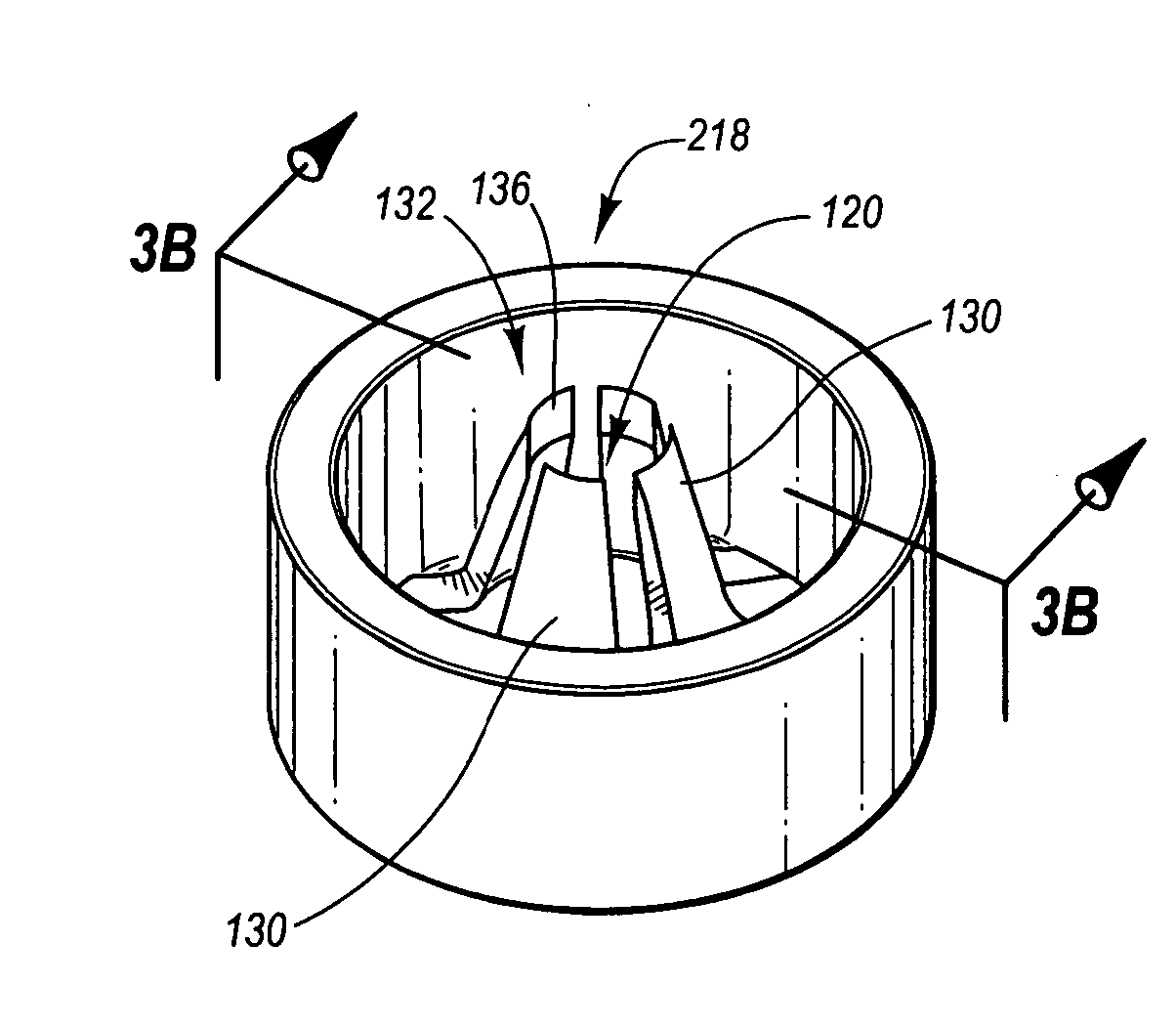
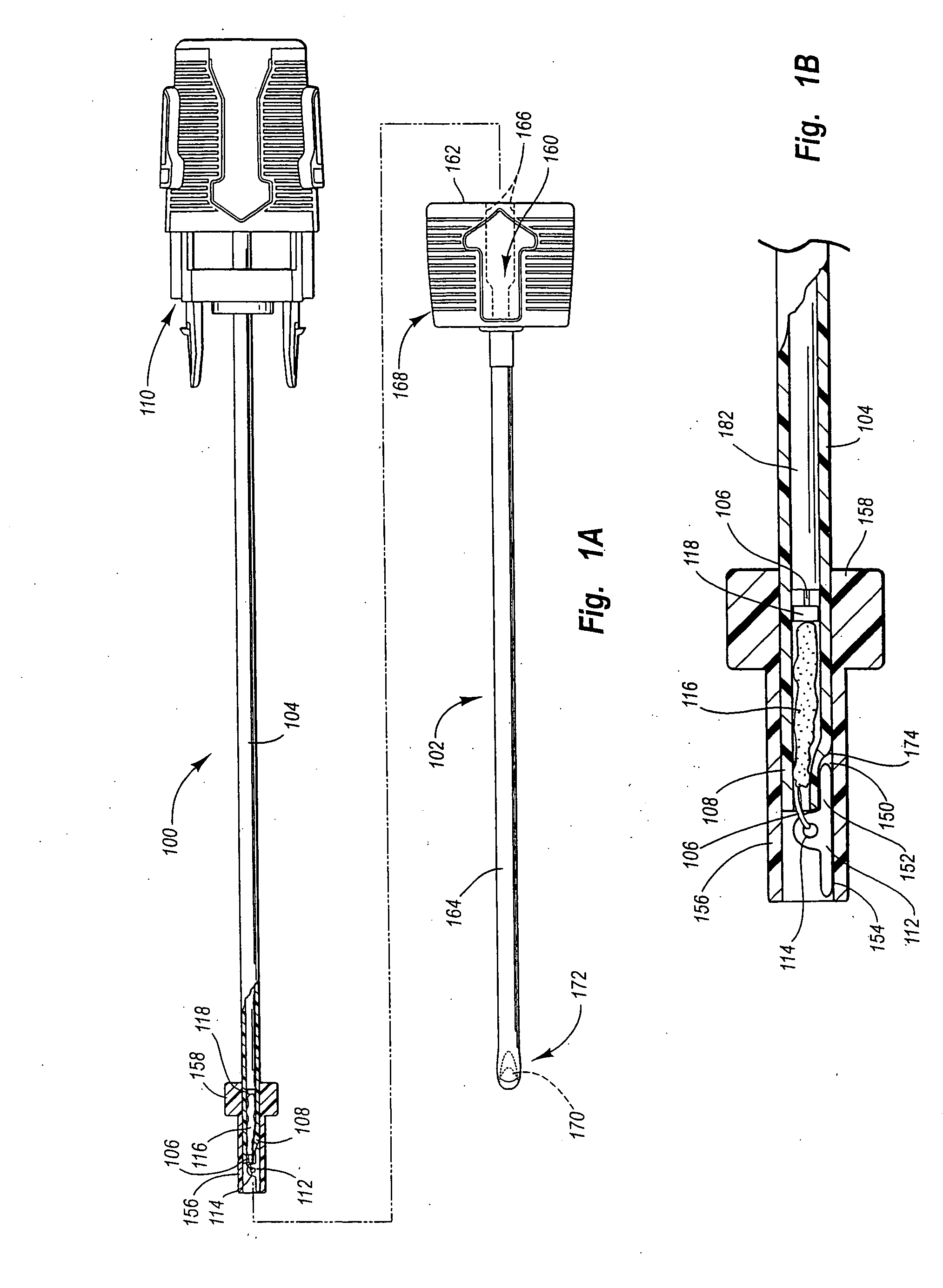
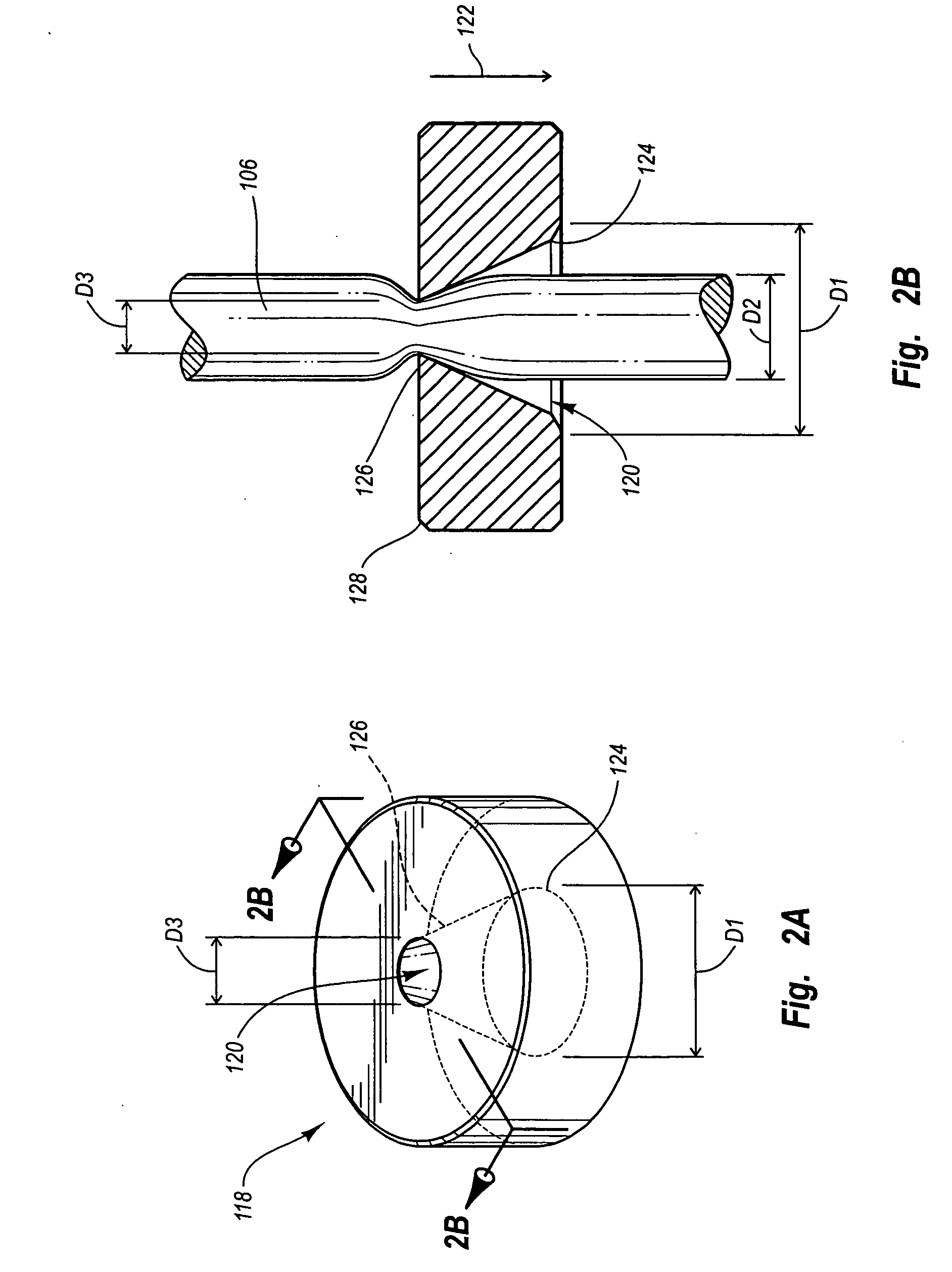
[0032] The present specification describes techniques and apparatus for closing an internal tissue wall puncture, preferably using a closure device and an introducer, while reducing the effects of sealing plug repositioning. While the methods and devices shown and described below include introducers and puncture sealing devices, the application of a locking apparatus to secure a sealing plug is not limited to these specific devices. The principles described herein may be used to hold a locking apparatus along a suture or other filament for any device, but may be particularly useful to retain a sealing plug at an internal tissue puncture. Therefore, while the description below is directed primarily to arterial procedures, the methods and apparatus may be used according to principles described herein with any filament to limit movement of a locking device to one direction along the filament.

[0033] As used in this specification and the appended claims, the term “tissue” means an aggre...


PUM


Abstract

An internal tissue puncture closure method and apparatus provides a locking device for compressing and holding an external component such as a collagen sponge at a puncture situs. The locking device facilitates compression of the external component in a first direction, but prevents or locks against retraction.

Description

FIELD OF THE INVENTION [0001] The present invention relates to medical devices, and, more particularly, to a vascular puncture closure apparatus. BACKGROUND OF THE INVENTION [0002] Various medical procedures, particularly cardiology procedures, involve accessing a corporeal vessel or other lumen through a percutaneous sheath. The access to the vessel necessarily requires the formation of a hole or puncture in the vessel wall so that a medical procedure can be performed. After the particular medical procedure has been performed, the sheath and other tools must eventually be removed from the vessel and the access hole in the vessel wall must be closed. [0003] A number of prior vascular closure devices have been developed to close the hole in the vessel wall. Closing the hole in the vessel wall typically involves packing a resorbable sealing plug at the hole or sandwiching the hole between the sealing plug and an anchor. Examples of prior vascular closure devices are described in U.S. ...

Claims


Application Information

Patent Timeline
Patent Type & Authority Applications(United States)
IPC IPC(8): A61B17/04
CPCA61B17/0057A61B2017/0496A61B2017/00654A61B2017/00637
Inventor WHITE, JOHNFORSBERG, ANDREW THOMAS
Owner KENSEY NASH HLDG
Why Eureka
Try Eureka