Vehicle occupant protection device

a protection device and occupant technology, applied in the direction of vehicular safety arrangments, pedestrian/occupant safety arrangements, vehicular components, etc., can solve the problems of excessive load not being applied to the pillar garnish from the front bag portion, and excessive load not being applied to the pillar garnish

Inactive Publication Date: 2006-03-23
HONDA MOTOR CO LTD
View PDF11 Cites 38 Cited by
  • Summary
  • Abstract
  • Description
  • Claims
  • Application Information

AI Technical Summary

Benefits of technology

[0024] Gas generated from the inflator flows through the gas inlets disposed in the longitudinally substantially middle portion into the gas main passages, and flows from the gas main passages to the front, middle and rear bag portions generally uniformly. As a result, the folded bag portions inflate, deploying along the side glasses toward the passenger compartment. All occupants seated in the front, middle and rear seats are properly and adequately protected.
[0037] The occupant protection device preferably further comprises a cover for covering the roof side airbag in a folded condition; and a clip including a head disposed within the cover and an engaging portion protruding outward from inside the cover; wherein the engaging portion is engaged with the vehicle body. Thus fitting the engaging portion to a mounting hole formed in the vehicle body facilitates mounting of the cover and the roof side airbag to the vehicle body. Consequently, the cover and the roof side airbag can be disposed without being dislocated from the vehicle body. The use of the clip simplifies the roof side airbag mounting structure.

Problems solved by technology

Therefore, when the front bag portion starts to deploy into the passenger compartment, an excessive load is not applied to the pillar garnish from the front bag portion.
Since the forward upper portion of the front bag portion inflates after the front bag portion deploys from the pillar space into the passenger compartment as described above, an excessive load is not applied to the pillar garnish.

Method used


Image

  • Vehicle occupant protection device
  • Vehicle occupant protection device
  • Vehicle occupant protection device

Examples


Embodiment Construction

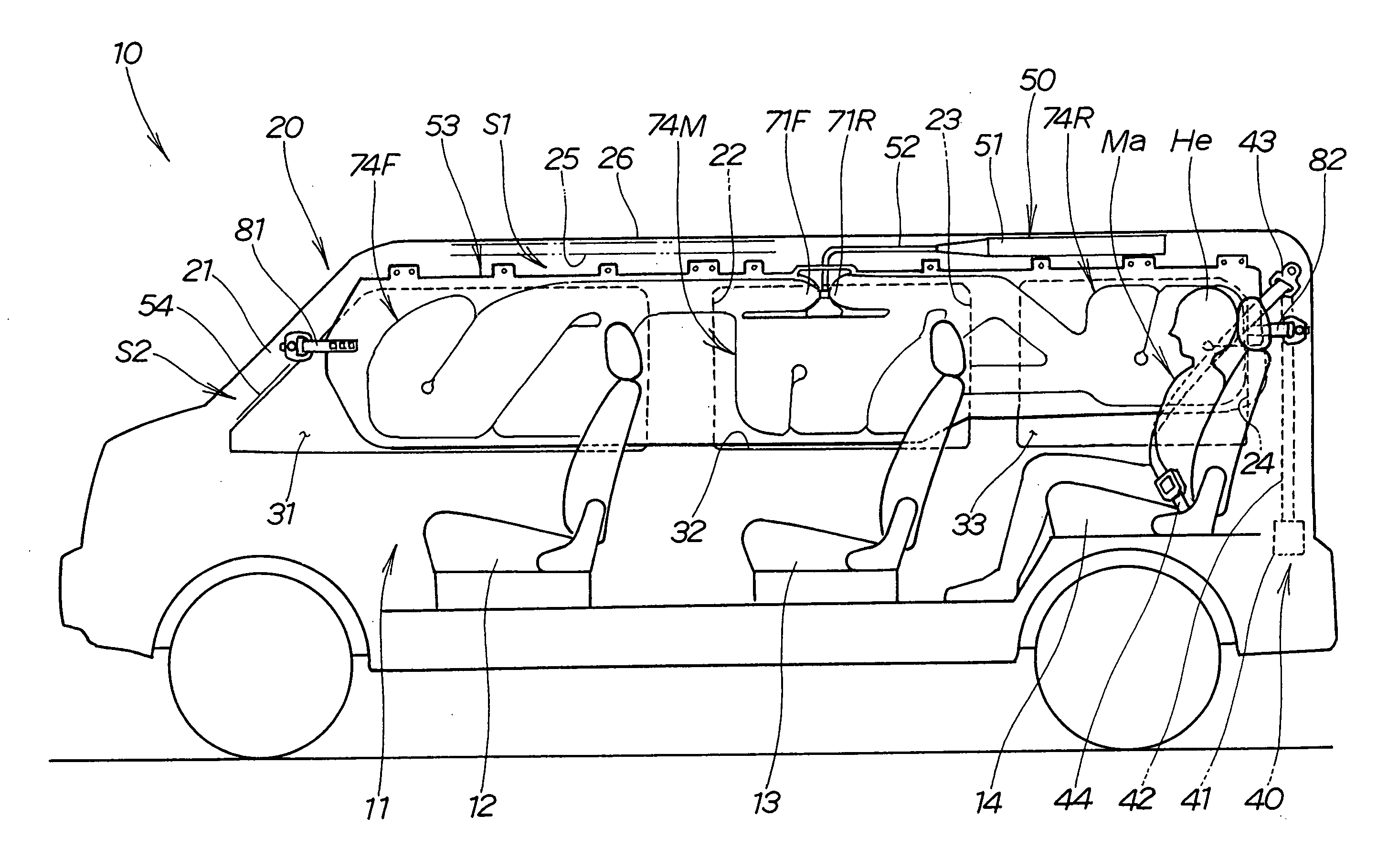
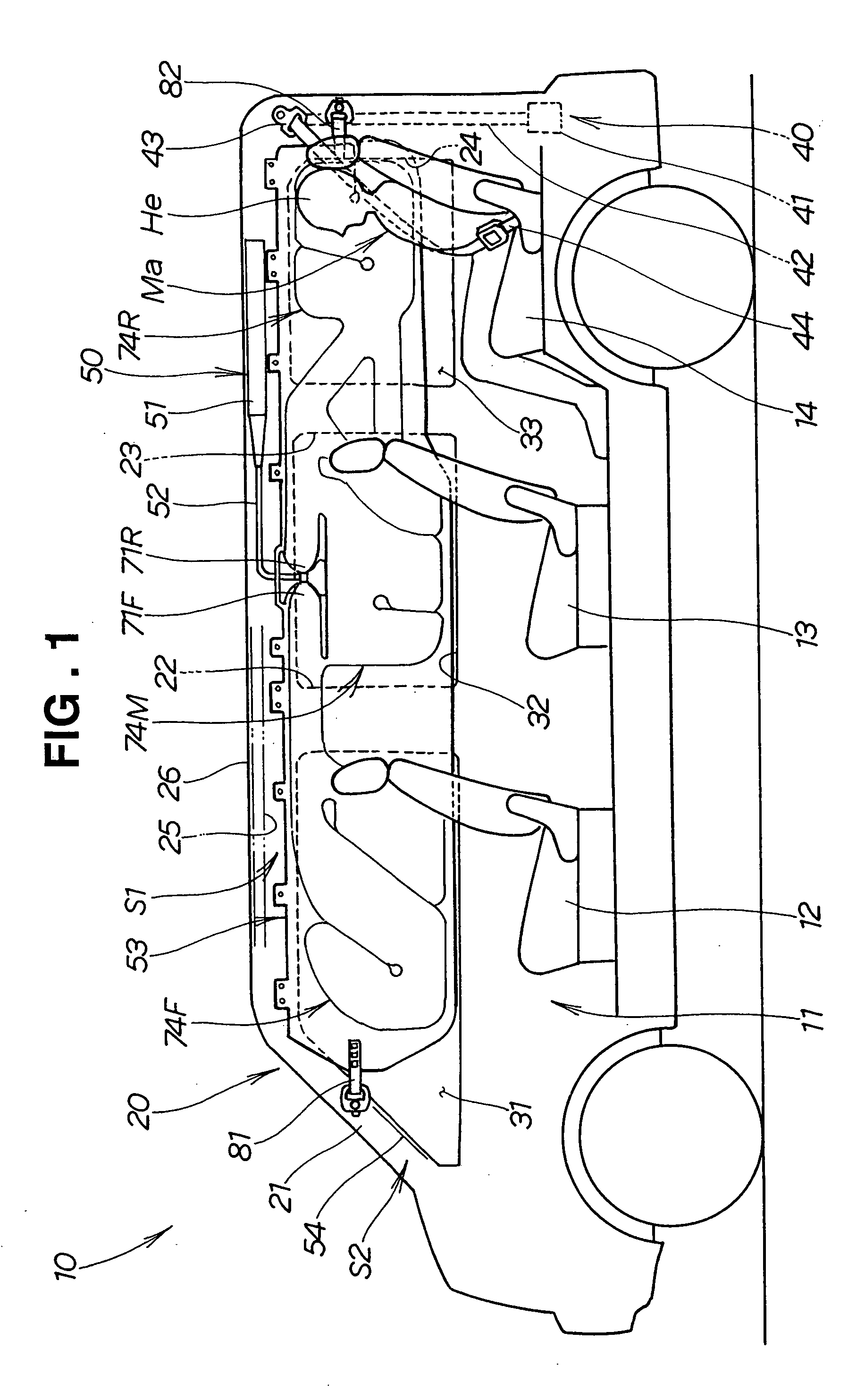
[0062] Initial reference is made to FIG. 1 showing a vehicle 10 provided with an occupant protection device 50. Actually, the occupant protection device 50 is provided on each side of a passenger compartment 11. The right and left occupant protection devices 50 have the same construction. Therefore, in this embodiment, only the occupant protection device 50 disposed on the right side of the vehicle 10 is illustrated for description, and description of the left-side occupant protection device 50 will be omitted.

[0063] The vehicle 10 shown in FIG. 1 is a station wagon with three rows of seats including a front seat 12, a middle seat 13 and a rear seat 14 in the passenger compartment 11. A vehicle body 20 includes a front pillar 21, a rear pillar 24, and a forward middle pillar 22 and a rearward middle pillar 23 provided therebetween. A roof side rail 25 is provided across the upper ends of the pillars 21, 22, 23 and 24. A roof 26 is supported by the roof side rail 25. A front side gl...


PUM


Abstract

An occupant protection device for a vehicle having several longitudinal rows of seats in a passenger compartment. The occupant protection device includes an inflator for generating gas and a longitudinally elongated roof side airbag mounted to a roof side rail. The roof side airbag includes a plurality of bag portions to inflate in positions corresponding to the rows of seats, respectively. Gas generated from the inflator flows through gas inlets disposed in a substantially middle portion of the roof side airbag into the bag portions generally uniformly, and the roof side airbag inflates along the inside of side glasses of the vehicle.

Description

FIELD OF THE INVENTION [0001] The present invention relates to an improvement in occupant protection devices configured to reinforce protection of occupants when a side of a vehicle is subjected to an impact force. BACKGROUND OF THE INVENTION [0002] In recent years, there have been developments for improving protection performance especially for the heads of occupants when a vehicle side is subjected to an impact force. [0003] Japanese Patent No. 3510061, for example, proposes an occupant protection device configured to store a roof side airbag from a pillar along a roof side edge so that the roof side airbag is inflated in the form of a curtain along side glasses when subjected to an impact force above a certain level. The roof side airbag is often called a side curtain airbag. [0004] This occupant protection device is configured so that the roof side airbag is stored in a pillar space and a roof space; an inflator is mounted to a roof side rail; the roof side airbag is mounted to ...

Claims


Application Information

Patent Timeline
Patent Type & Authority Applications(United States)
IPC IPC(8): B60R21/16B60R21/20B60R21/201B60R21/232B60R21/233B60R21/2346B60R21/26B60R21/261
CPCB60R21/201B60R21/232B60R2021/2617B60R21/26B60R21/2346
Inventor AOKI, TAKASHITOTSUKA, HIROFUMISAITO, YUICHI
Owner HONDA MOTOR CO LTD
Why Eureka
Try Eureka