Reventing point of impact shift

a technology of impact shift and point, applied in the field of variable focus system, can solve the problems of reducing the yield of assembled devices, increasing the cost of fabrication, and affecting the image point of impact shift, so as to prevent the point of impact shift

Inactive Publication Date: 2006-03-23
ASIA OPTICAL CO INC
View PDF2 Cites 7 Cited by
  • Summary
  • Abstract
  • Description
  • Claims
  • Application Information

AI Technical Summary

Benefits of technology

[0009] Accordingly, at least one objective of the present invention is to provide a mechanism for preventing point of impact shift when the focus is changed in a variable focus system.
[0015] The present invention provides a mechanism for preventing point of impact shift. The mechanism relies on an elastically deformed first and a second arresting spring inside a groove to press against the internal sleeve so that the area in first and the second lens chamber located diametrically opposite to the groove also presses against the internal sleeve. Therefore, the first and the second lens chamber can slide within the internal sleeve with very little wobble. In other words, the mechanism in the present invention for preventing the point of impact shift in a variable focus system can stabilize the sliding action of the first and the second lens chamber when the focus is changed.

Problems solved by technology

Ultimately, this may lead to a point of impact shift in the image.
However, increasing the precision means a higher cost of fabrication or a drop in the yield of the assembled device.

Method used


Image

  • Reventing point of impact shift
  • Reventing point of impact shift
  • Reventing point of impact shift

Examples


Embodiment Construction

[0024] Reference will now be made in detail to the present preferred embodiments of the invention, examples of which are illustrated in the accompanying drawings. Wherever possible, the same reference numbers are used in the drawings and the description to refer to the same or like parts.

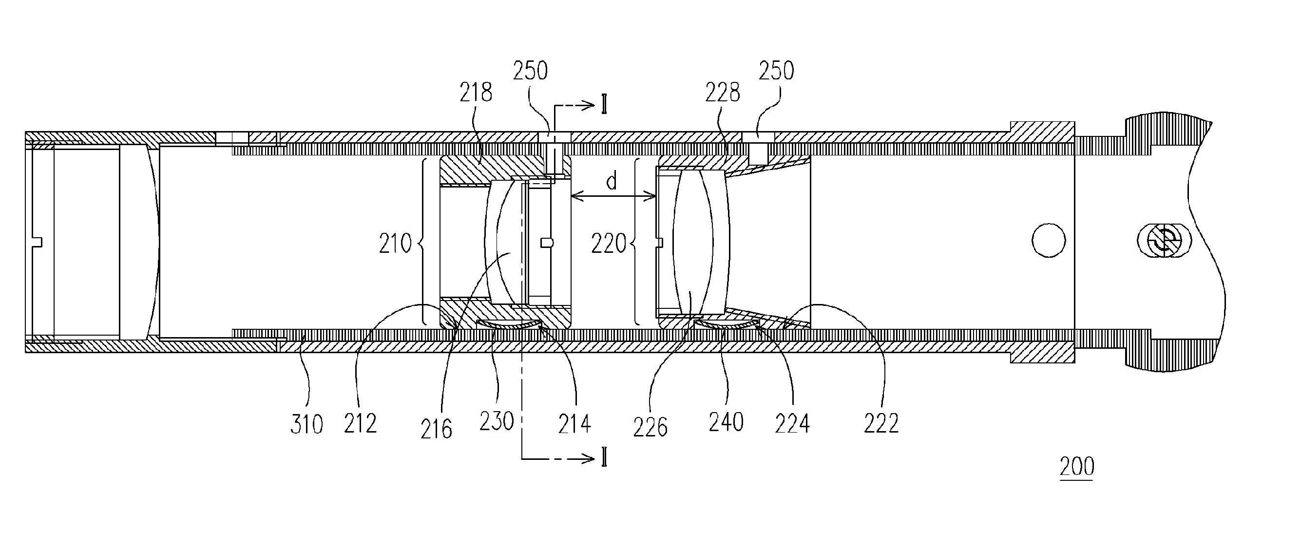
[0025]FIG. 3 is a schematic cross-sectional view showing a mechanism for prevention point of impact shift disposed inside an internal sleeve according to the present invention. FIG. 4 is a schematic cross-sectional view along line I-I′ of FIG. 3. As shown in FIGS. 3 and 4, the mechanism 200 for preventing point of impact shift in the present embodiment is commonly adapted to a variable focus system (not shown) such as an aiming device for shooting. The mechanism 200 for preventing point of impact shift comprises a first lens chamber 210, a second lens chamber 220, a first arresting spring 230 and a second arresting spring 240. The first lens chamber 210 and the second lens chamber 220 are disposed ...


PUM


Abstract

A mechanism for preventing point of impact shift inside a variable focus system. The mechanism for preventing point of impact shift comprises a first lens chamber, a second lens chamber, a first arresting spring and a second arresting spring. The first and the second lens chamber are disposed within an internal sleeve but separated from each other by a distance. The first and the second lens chamber can slide within the internal sleeve and each lens chamber has an individual groove. The first arresting spring is disposed inside the groove in the first lens chamber such that the first arresting spring is elastically deformed between the internal sleeve and the first lens chamber. The second arresting spring is disposed inside the groove in the second lens chamber such that the second arresting spring is elastically deformed between the internal sleeve and the second lens chamber.

Description

CROSS-REFERENCE TO RELATED APPLICATION [0001] This application claims the priority benefit of Taiwan application serial No. 93128689, filed Sep. 22, 2004. BACKGROUND OF THE INVENTION [0002] 1. Field of the Invention [0003] The present invention relates to a variable focus system. More particularly, the present invention relates to a mechanism for preventing point of impact shift inside a variable focus system. [0004] 2. Description of the Related Art [0005] With the rapid development of high-tech equipment in recent years, many types of optical devices including cameras, digital cameras, projectors, telescopes and aiming device are designed with a variable focus system to meet the needs of users. All these optical devices with variable focusing capability frequently utilize a variable focus mechanism to change the relative position between the different lenses and provide a zooming effect. [0006]FIG. 1 is a split-up view of various components constituting a conventional variable foc...

Claims


Application Information

Patent Timeline
Patent Type & Authority Applications(United States)
IPC IPC(8): G02B7/02F41G1/38G02B7/10G02B23/14
CPCF41G1/38G02B23/14G02B7/10
Inventor LIN, CHEN-YEH
Owner ASIA OPTICAL CO INC
Why Eureka
Try Eureka