Shockproof cover cutting structure

a cutting structure and cover technology, applied in the field of air column structure, can solve the problems of air leakage and loss of cushioning function, and achieve the effect of preventing the tearing poin

Inactive Publication Date: 2012-11-22
LIAO YAW SHIN
View PDF1 Cites 0 Cited by
  • Summary
  • Abstract
  • Description
  • Claims
  • Application Information

AI Technical Summary

Benefits of technology

The present invention provides a cutting structure for a shockproof cover that prevents tearing points from extending linearly along a cutting line between air columns. This is achieved by using at least one cutting line between two air columns that can separate the adjacent air columns towards different directions, allowing air column pieces to be separated into two pieces and rotating freely. A through hole is also included at the top end of the cutting line where the two cutting lines intersect to prevent the tearing point from extending linearly along the cutting line and ripping the air column. Additionally, the shockproof cover cutting structure has increased strength and thickness with the use of a strengthening layer that tightly attaches to the air column piece. This prevents the cutting line from further tearing and extending.

Problems solved by technology

Or, the column wall of the air column is thinned and is very likely to be punctured by the object it is covering, causing air leakage and loss of cushioning function.

Method used


Image

  • Shockproof cover cutting structure
  • Shockproof cover cutting structure
  • Shockproof cover cutting structure

Examples


Embodiment Construction

[0017]The above and further objects and novel features of the invention will more fully appear from the following detailed description when the same is read in connection with the accompanying drawing. It is to be expressly understood, however, that the drawing is for purpose of illustration only and is not intended as a definition of the limits of the invention.

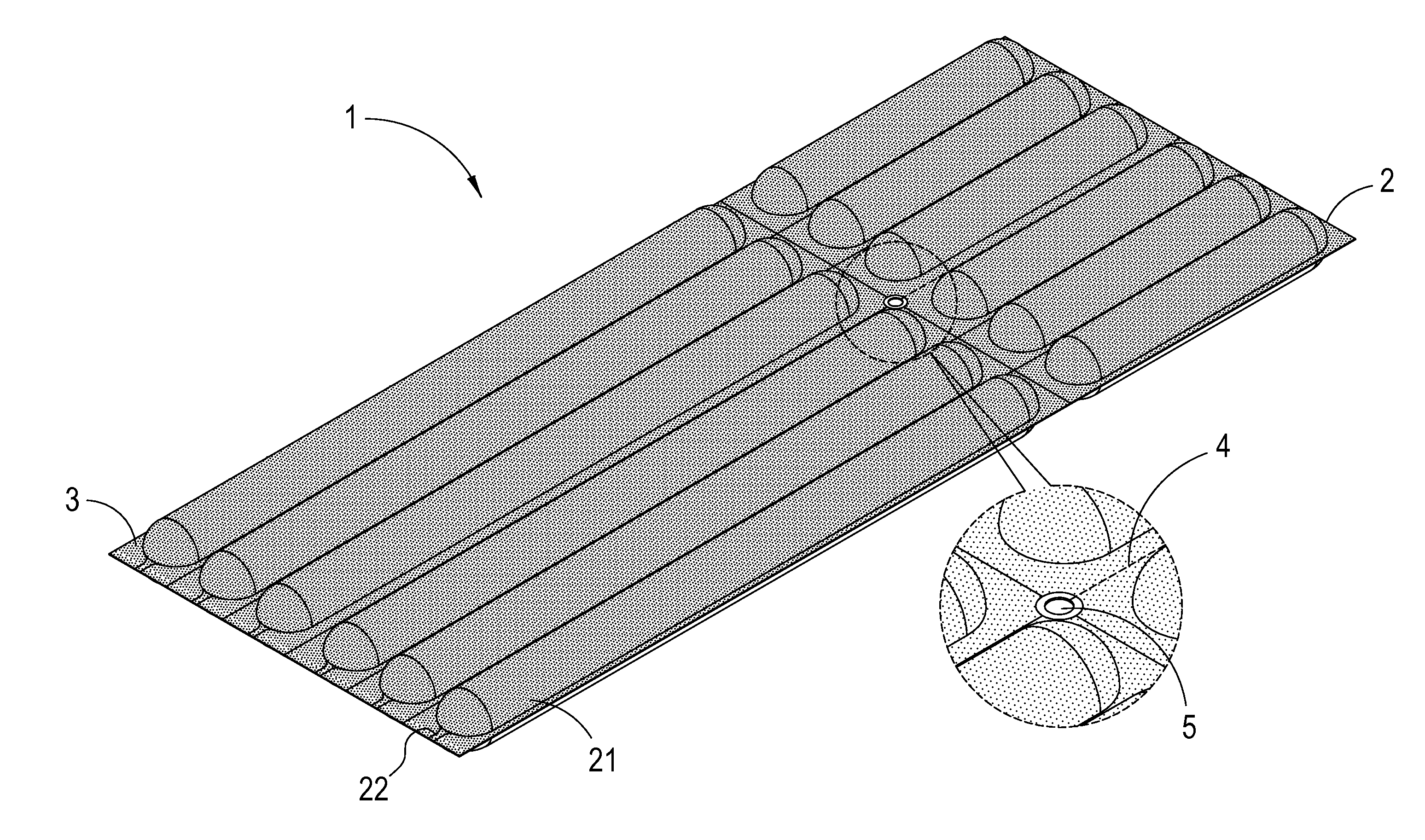
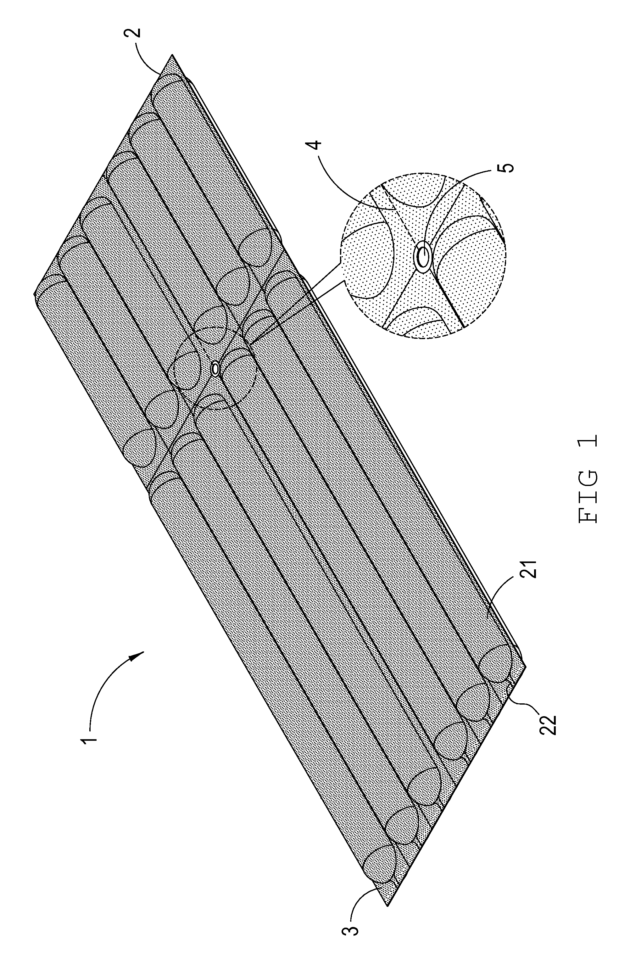
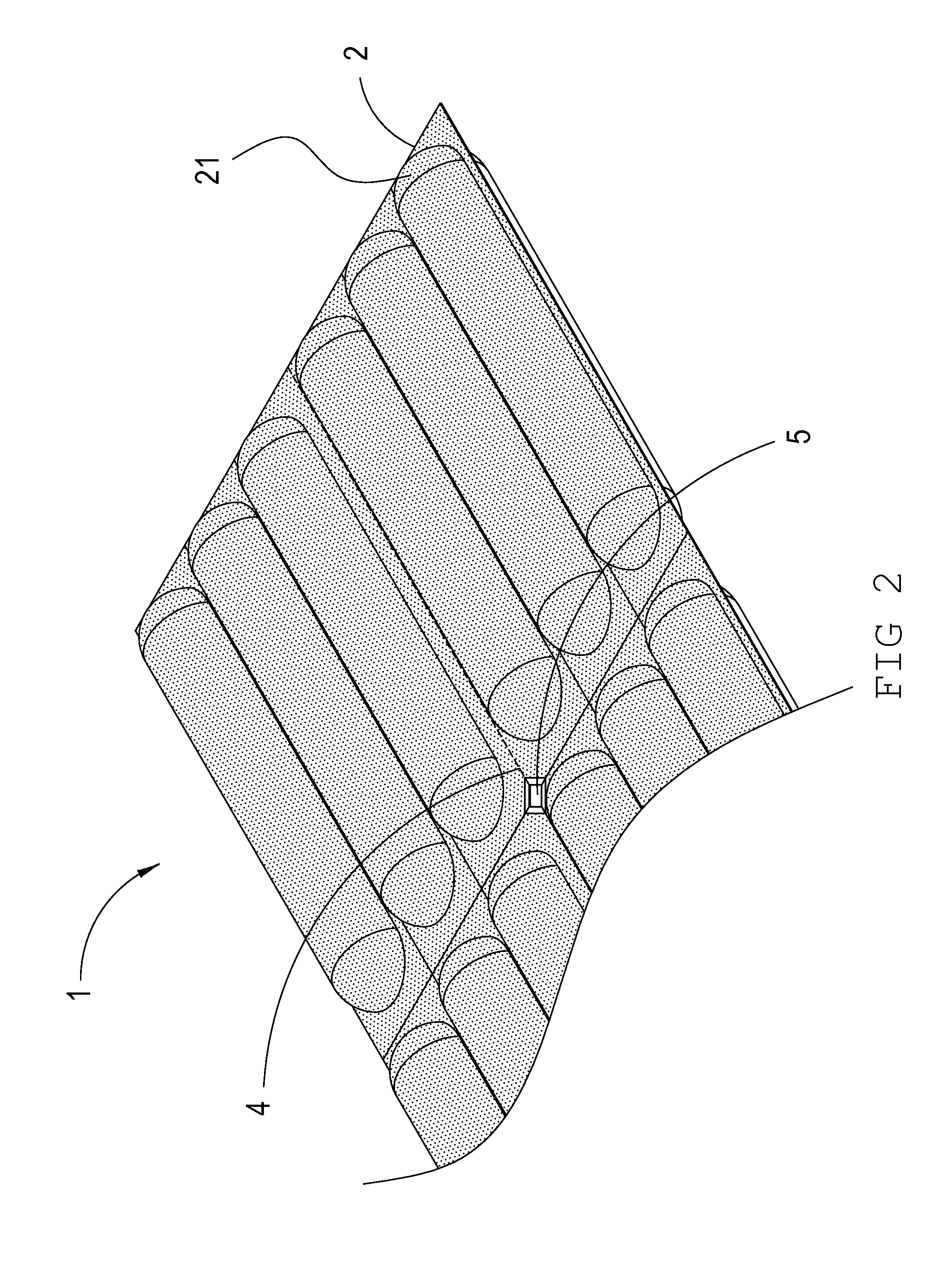
[0018]Please refer to FIGS. 1 to 6 first, which illustrate the appearance perspective view, partial schematic view and preferred embodiment of the present invention. A shockproof cover cutting structure 1 is provided therein, which includes: an air column piece 2 parallel consists of a plurality of air columns 21, each of the air columns 21 is disposed of an air inflation inlet 22, and by the air inflation inlet 22 it is able to inflate the plurality of air columns 21 to form a cushion packaging effect and protect an object covered therein;

a strengthening layer 3 attached to any one side of or both sides of the air column pi...


PUM

PropertyMeasurementUnit
sizeaaaaaaaaaa
thicknessaaaaaaaaaa
strengthaaaaaaaaaa

Abstract

Disclosed is a shockproof cover cutting structure. At least one cutting line is provided between two air columns, wherein the cutting line is capable of separating the adjacent two air columns towards different directions, thereby allowing air column piece to be separated into two pieces and capable of rotating freely. Further, a through hole is disposed at top end of the cutting line where the two cutting lines of the two air columns intersect. When the two air columns are separated towards different directions, the through hole is capable of preventing the tearing point from extending linearly along the cutting line and ripping the air column thereof. Or, to prevent the column wall of the air column from being thinned and likely to be punctured by the object it is covering, causing air leakage and loss of cushioning function.

Description

BACKGROUND OF THE INVENTION[0001]1. Field of the Invention[0002]The present invention relates to an air column structure, and more particularly to a cutting structure for shockproof cover.[0003]2. Brief Description of the Related Art[0004]Existing cushion packaging method is to use air packing bag as the cushion material, wherein the air packing bag has two plastic films and an inner film with an air stop structure. The inner film thereof consists of two inner films and is disposed of an air inflation inlet; after air inflation, air column can be formed for air sealing. The air column is often required to bend with object's shape to cover the object completely and provide cushioning effect. Hence, hot melt point is often used to allow the air column to have turning point, and thereby being able to bend.[0005]For instance, the prior art “An air-packing device,” patent number: U.S. Pat. No. 7,584,848, is described below.[0006]An air-packing device inflatable by compressed air for prot...

Claims


Application Information

Patent Timeline
Patent Type & Authority Applications(United States)
IPC IPC(8): B32B1/08
CPCB32B1/08Y10T428/1334B32B2439/00B32B5/022
Inventor LIAO, YAW SHIN
Owner LIAO YAW SHIN
Why Eureka
Try Eureka