Wireless power transmission apparatus and wireless power transmission system

a power transmission apparatus and wireless technology, applied in power conversion systems, dc-dc conversion, climate sustainability, etc., can solve the problems of low reliability and unintended characteristics of the operating point, and achieve the effect of preventing resonance points and high reliability

Active Publication Date: 2021-09-30
TDK CORPARATION
View PDF0 Cites 2 Cited by
  • Summary
  • Abstract
  • Description
  • Claims
  • Application Information

AI Technical Summary

Benefits of technology

The technology described in the patent text aims to prevent unintended characteristic resonance points from becoming operating points, resulting in a more reliable wireless power transmission system.

Problems solved by technology

However, if there are three resonance points, since the characteristics will change in accordance with the resonance point that serves as the operating point, depending on the operating point, there is a risk that the operating point will be a resonance point with unintended characteristics.
Thus, the reliability is low and there is still room for improvement.

Method used


Image

  • Wireless power transmission apparatus and wireless power transmission system
  • Wireless power transmission apparatus and wireless power transmission system
  • Wireless power transmission apparatus and wireless power transmission system

Examples


Embodiment Construction

[0019]Hereinafter, embodiments of the technology according to the present disclosure will be explained in detail with reference to the drawings.

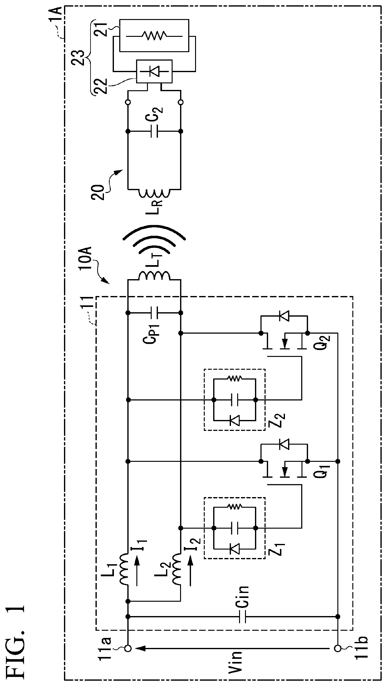
[0020]FIG. 1 is a circuit diagram illustrating an example of the structure of a wireless power transmission system according to an embodiment in the present disclosure.

[0021]As illustrated in FIG. 1, the wireless power transmission system 1A is provided with a wireless power transmission apparatus 10A and a wireless power reception apparatus 20 that receives electric power transmitted by the wireless power transmission apparatus 10A. This wireless power transmission system 1A wirelessly transmits electric power from the wireless power transmission apparatus 10A to the wireless power reception apparatus 20.

[0022]The wireless power transmission apparatus 10A is provided with a power transmission coil LT that transmits electric power; a power transmission-side resonant capacitor Cp1 that is parallel-connected to the power transmission coil LT a...


PUM


Abstract

A wireless power transmission apparatus including a power transmission coil that transmits electric power; a power transmission-side resonant capacitor that is connected to the power transmission coil and that, with the power transmission coil, forms a power transmission-side resonance circuit; and a self-oscillation circuit that converts a DC voltage to an AC voltage, and that supplies the AC voltage to the power transmission coil. The wireless power transmission apparatus has a state, during power transmission, in which multiple resonance points exist in a combined resonance circuit formed by magnetic coupling of the power transmission-side resonance circuit with a power reception-side resonance circuit formed from a power reception coil and a power reception-side resonant capacitor. In the state, the self-oscillation circuit operates at the lowest frequency among the multiple resonance points.

Description

BACKGROUND OF THE INVENTIONField of the Invention[0001]The present disclosure relates to a wireless power transmission apparatus and a wireless power transmission system.[0002]Priority is claimed on Japanese Patent Application No. 2020-064506, filed Mar. 31, 2020, the content of which is incorporated herein by reference.Description of Related Art[0003]Conventionally, wireless power transfer technologies for transmitting electric power without using power cables are known. Wireless power transfer technologies are technologies that can be expected to be highly convenient, such as by making both the power-transmitting side and the power-receiving side wireless. Thus, in recent years, the application of these technologies to product fields such as those of compact devices, including cellular telephones, has been advanced. Examples of wireless power transfer systems include electromagnetic induction systems, magnetic field resonance systems, electric field resonance systems, microwave sy...

Claims


Application Information

Patent Timeline
Patent Type & Authority Applications(United States)
IPC IPC(8): H02J50/12H02J50/80
CPCH02J50/12H02J50/80H02M3/338H02M3/3372H02M1/32H02M1/0058Y02B70/10
Inventor YONEDA, KAZUKI
Owner TDK CORPARATION
Why Eureka
Try Eureka