Fading simulator and fading simulation method

Active Publication Date: 2013-10-03
ANRITSU CORP
View PDF2 Cites 4 Cited by
  • Summary
  • Abstract
  • Description
  • Claims
  • Application Information

AI Technical Summary

Benefits of technology

The invention is for a device and method that can simulate fading during a test without creating any sudden disruptions in the signal. This means that the device can adjust its settings without causing any problems during the test.

Problems solved by technology

As a result, code errors increase in a digital communication environment, and transmission qualities considerably deteriorate.

Method used


Image

  • Fading simulator and fading simulation method
  • Fading simulator and fading simulation method
  • Fading simulator and fading simulation method

Examples


Embodiment Construction

[0040]Hereinafter, an embodiment of the present invention will be described with reference to the accompanying drawings.

[0041]First, a configuration in an embodiment of a fading simulator according to the present invention will be described.

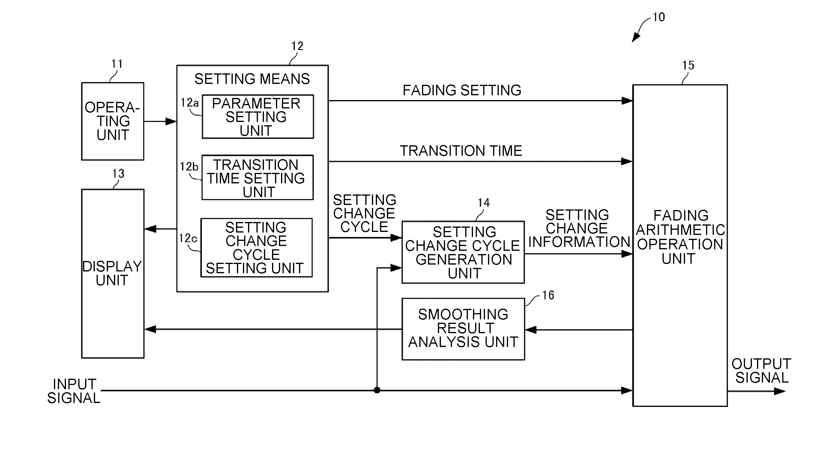
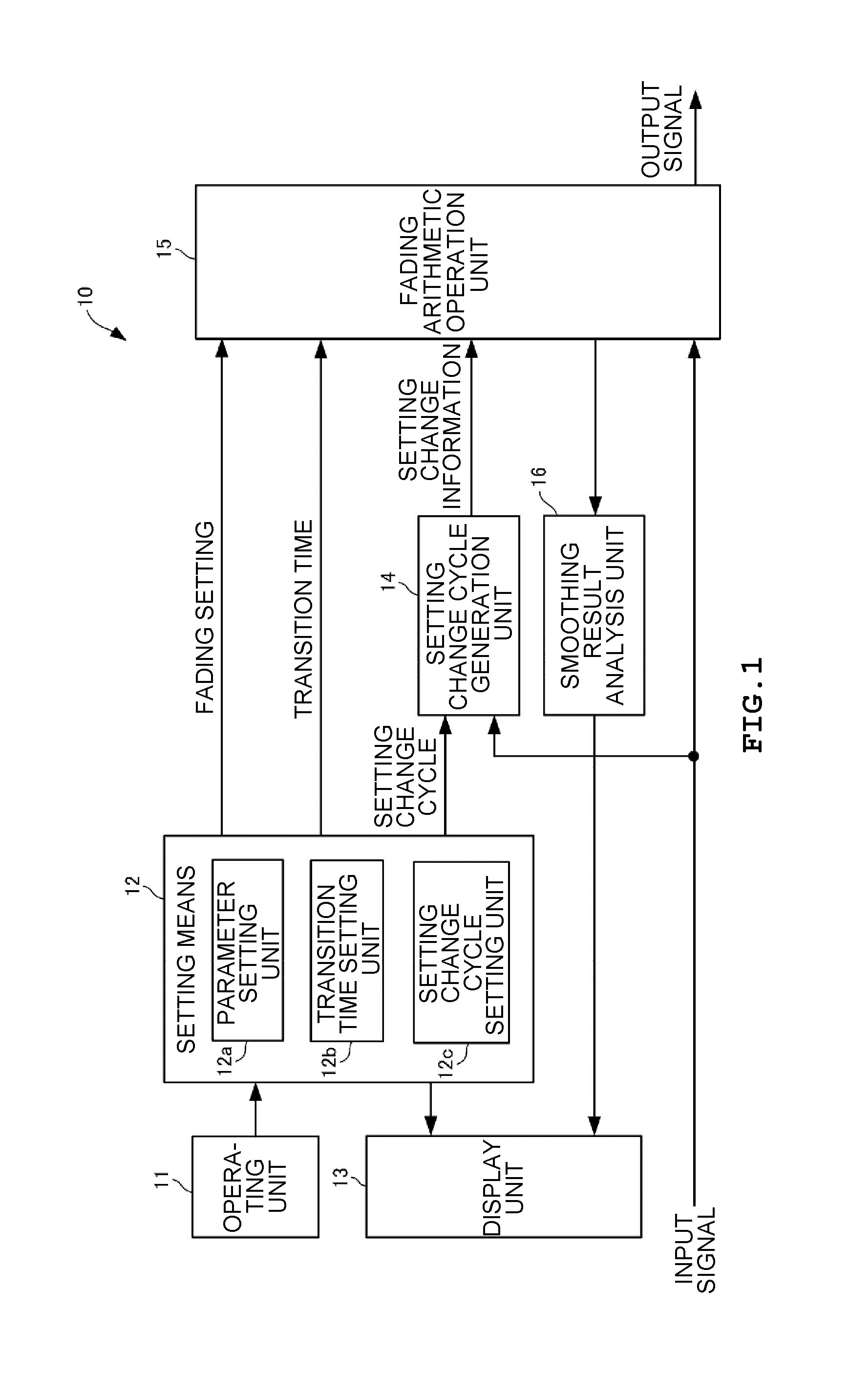
[0042]As shown in FIG. 1, a fading simulator 10 includes an operating unit 11, a setting means 12, a display unit 13, a setting change cycle generation unit 14, a fading arithmetic operation unit 15, and a smoothing result analysis unit 16. The fading simulator 10 simulates MIMO-type M×N transmission paths. Meanwhile, a signal which is input and output by the fading simulator 10 is set to a digital signal.

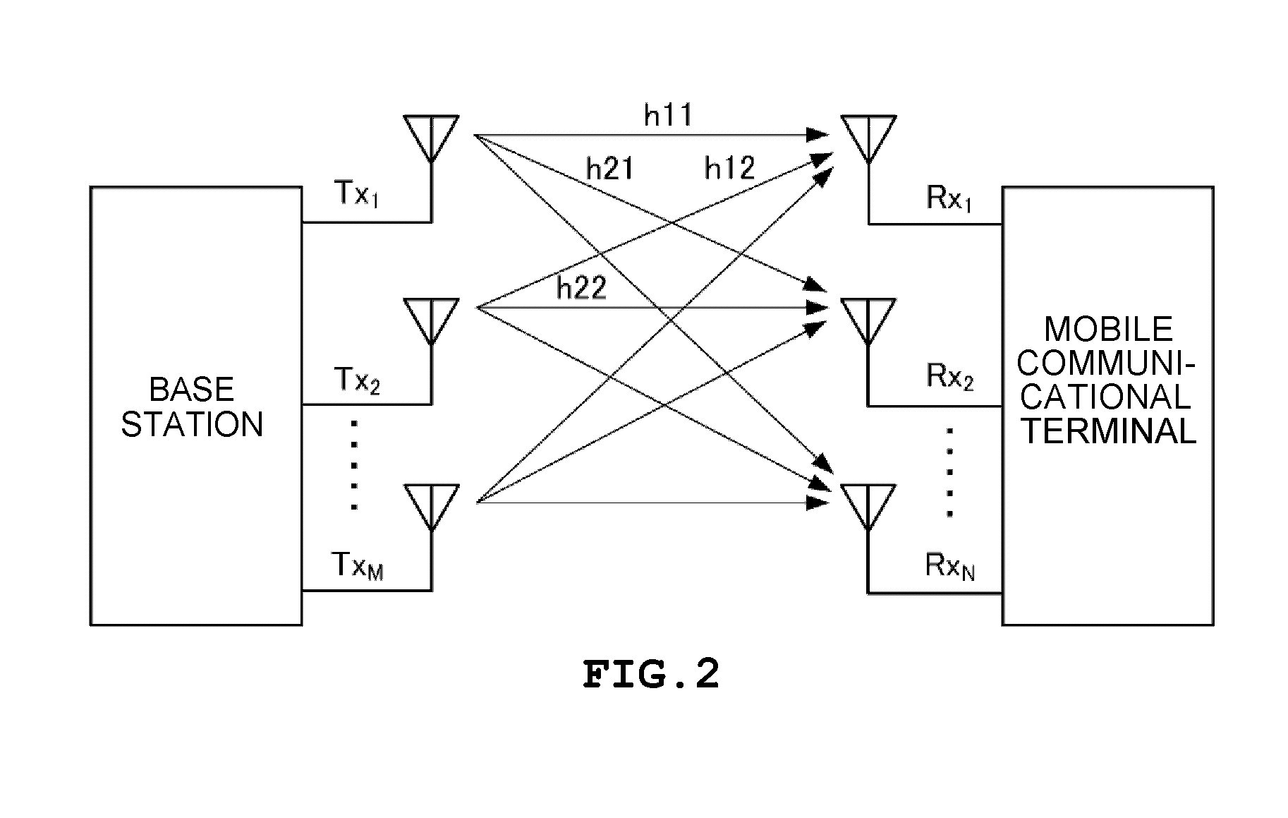
[0043]As shown in FIG. 2, the MIMO type is designed to simultaneously output information, desired to be transmitted to a mobile communication terminal at the base station side, from a plurality of (M) antennas Tx1, Tx2, . . . , TxM at the same frequency, cause the mobile communication terminal to receive the information at a plurality of (N) ant...


PUM


Abstract

A fading simulator includes a transition time setting means that sets up a predetermined transition time, at the time of switching of a fading setting using a fading parameter, between the fading setting before switching and the fading setting after switching, and a smoothing processing means that smoothly changes a value before the switching to a value after the switching with respect to at least one of a delay parameter, a Doppler effect parameter and a path loss parameter, during the transition time.

Description

TECHNICAL FIELD[0001]The present invention relates to a fading simulator and a fading simulation method for simulating a radio wave propagation environment with respect to a mobile communication terminal such as, for example, a cellular phone or a mobile terminal.BACKGROUND ART[0002]In recent years, mobile communication terminals such as cellular phones or mobile terminals have been rapidly developed. Radio waves reaching mobile communication terminals from a base station are changed to multiple waves by reflection, scattering, diffraction or the like due to the geographical features of a propagation path thereof, structures or the like, and the amplitude and phase of radio waves vary randomly with location. When radio waves from a base station are received while moving within the propagation path, fading due to the multi-path propagation of radio waves occurs. As a result, code errors increase in a digital communication environment, and transmission qualities considerably deteriora...

Claims


Application Information

Patent Timeline
IPC IPC(8): H04W24/06H04B17/00H04B17/391
CPCH04W24/06H04W24/00
Inventor SUENAGA, AKIHIKONAKAO, KENICHITAKAGI, MOTOHIRO
Owner ANRITSU CORP
Why Eureka
Try Eureka