Self-adjusting RF assembly

a radio frequency and assembly technology, applied in the direction of modulation, subscriber indirect connection, sensing record carrier, etc., can solve the problems of degrading the range of a tag reading system, increasing electromagnetic radiation in one or more directions,

Inactive Publication Date: 2006-03-30
TAGSYS
View PDF2 Cites 226 Cited by
  • Summary
  • Abstract
  • Description
  • Claims
  • Application Information

AI Technical Summary

Benefits of technology

[0021] The present invention proposes a self adjusting RF assembly including an RF radiator. The RF assembly includes one or more components that may be replaced by a user. The components may include antennae, external antenna multiplexers, manufacturer supplied cable assemblies, and / or associated system and sub-system components. In the case of multiple antenna channels, an identification element may be applied to each antenna that is to be attached to the RF assembly. The identification element may allow the monitoring element to identify the antenna or associated component or components by a unique serial number or by a model number or by peak realised gain or the like. Upon identification of the antenna or component, the adjusting element may adjust output power of the RF assembly to a level consistent with local EMC regulations within which the assembly should be operated. In the event that the end-user connects an unidentified or unknown antenna or component to the assembly, ie. an antenna or component other than those specified by the manufacturer, the assembly may be placed into an inoperative state, such that presence of the unidentified or unknown antenna or component may not cause the assembly to exceed the local EMC regulations. This feature may include non-operation of the assembly without an antenna to protect the assembly from reflective overload. New antenna models or components may be included by updated reader firmware or certified and stored in memory by connecting to a database, with the update containing the model and / or serial numbers of permitted components.

Problems solved by technology

This may lead to increased electromagnetic radiation in one or more directions that may possibly exceed the local EMC regulations.
The necessity for such a conservative approach degrades the range of a tag reading system since it is often configured with antennae having gains less than the maximum offered by the manufacturer of the tag reading system.
Moreover under current EMC regulation regimes, certifying a system with the highest gain antenna does not prevent an end-user from being irresponsible, but merely serves to protect the manufacturer against usage of their product outside of its intended parameters.

Method used


Image

  • Self-adjusting RF assembly
  • Self-adjusting RF assembly
  • Self-adjusting RF assembly

Examples


Embodiment Construction

[0027] Preferred embodiments of the present invention will now be described with reference to the accompanying drawings wherein:

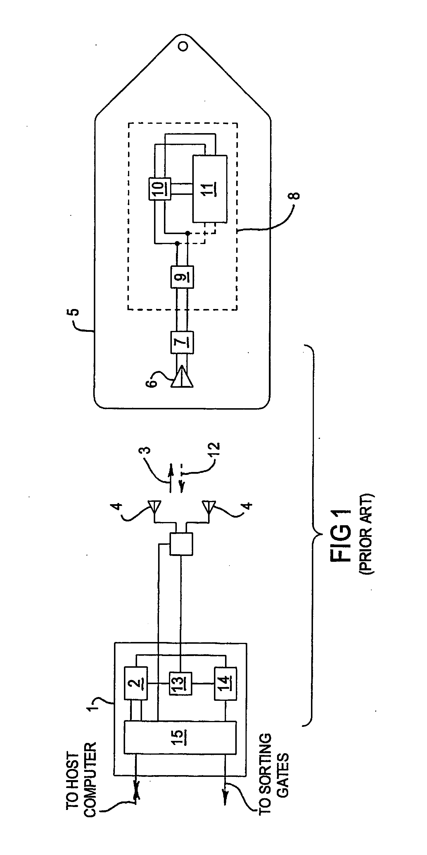
[0028]FIG. 1 shows major elements of a prior art object management system;

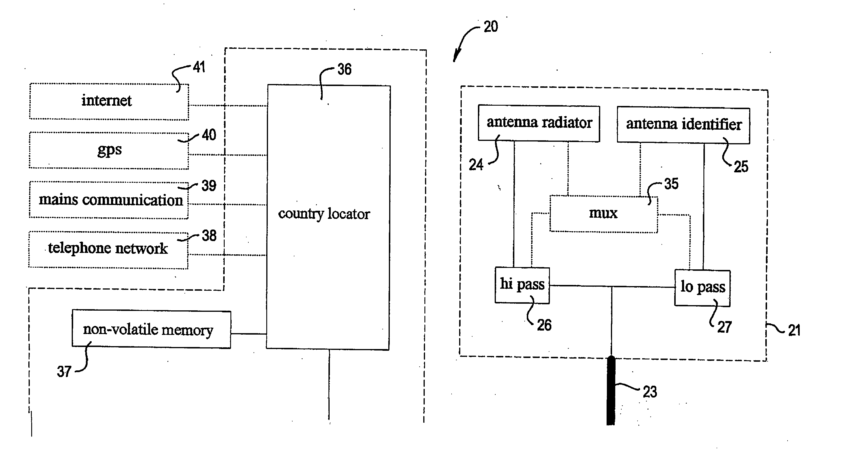
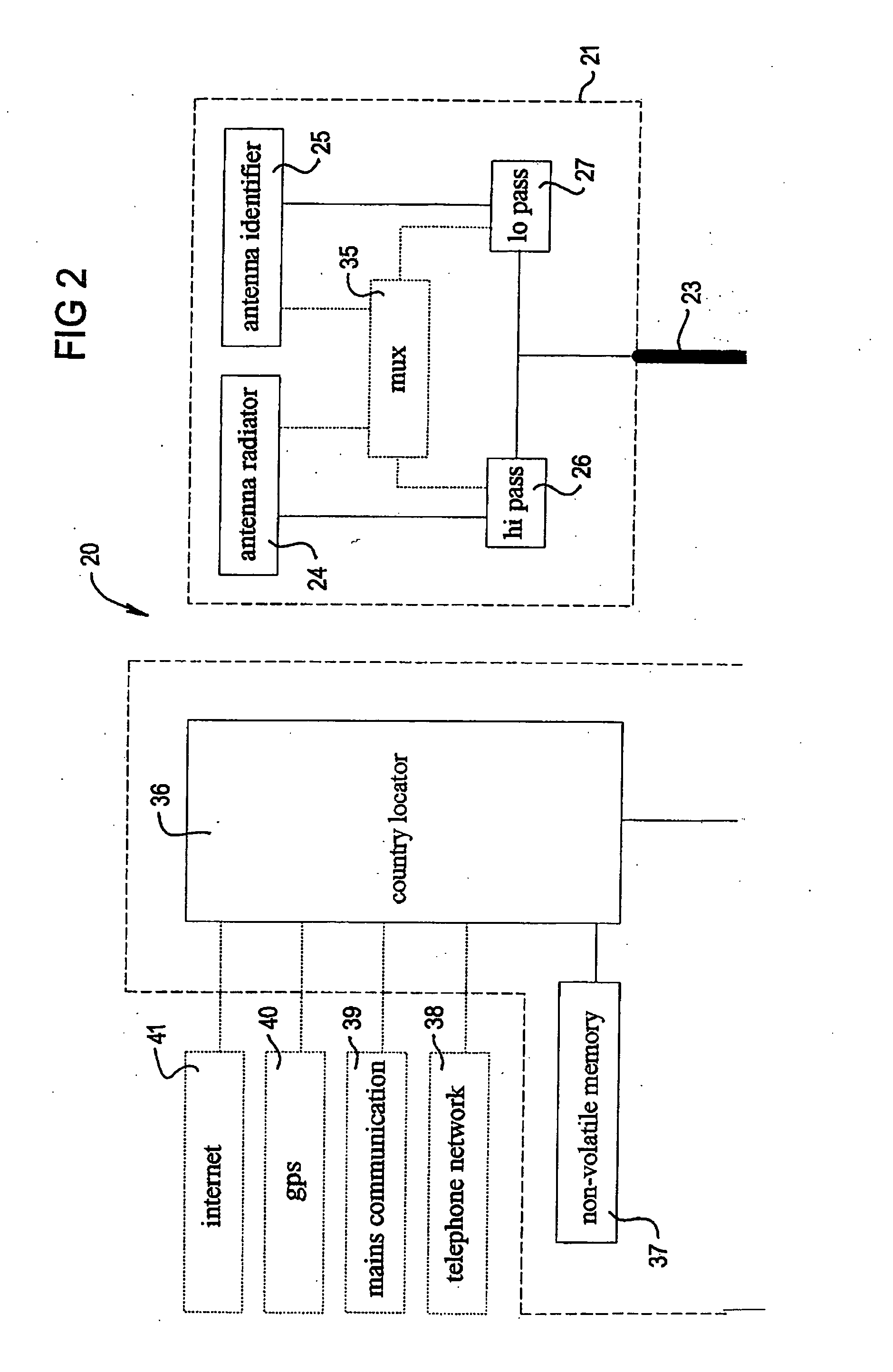
[0029]FIG. 2 shows one embodiment of an interrogator incorporating a self adjusting component identification system according to the present invention;

[0030]FIG. 3 shows an analog circuit for measuring a resistance associated with an antenna radiator;

[0031]FIG. 4 shows a digital circuit for measuring a resistance associated with an antenna radiator;

[0032] FIGS. 5 shows a circuit for reading an RFID chip associated with an antenna radiator;

[0033]FIG. 6 shows another circuit for reading an RFID chip associated with an antenna radiator; and

[0034]FIG. 7 shows a further circuit for reading an RFID chip associated with an antenna radiator.

[0035]FIG. 1 shows a typical arrangement of an interrogator system in which an interrogator 1 containing a transmitter 2 generates an electromagne...


PUM


Abstract

A self adjusting RF assembly including an RF radiator is disclosed. The RF assembly includes at least one component that may be replaced by a user of the RF assembly. The RF assembly includes an identification element associated with the at least one component for representing at least one characteristic of the component. The RF assembly includes a monitoring element for monitoring the identification element at least during power up of the RF assembly. The RF assembly also includes an adjusting element for adjusting radiation from the RF radiator wherein the adjusting element is operably associated with the monitoring element to maintain radiation from the RF radiator below a preset limit. The preset limit is typically determined by local electromagnetic compatibility (EMC) regulations. A method for maintaining radiation from an RF assembly below a preset limit is also disclosed.

Description

FIELD OF THE INVENTION [0001] The present invention relates to a self-adjusting radio frequency (RF) assembly that includes an RF radiator. In particular the present invention relates to a system for facilitating compliance with local electromagnetic compatibility (EMC) regulations at least when the RF assembly is reconfigured. The present invention has particular application in the field of radio frequency identification (RFID) tags that may be attached to objects which are to be used to identify, sort, control and / or audit the objects. BACKGROUND OF THE INVENTION [0002] The RFID tags may be part of an object management system and may include information passing between an interrogator which creates an electromagnetic interrogation field and the RFID tags, which may respond by issuing a reply signal that is detected by the interrogator, decoded and consequently supplied to other apparatus in the sorting, controlling or auditing process. The objects to which the tags are attached ma...

Claims


Application Information

Patent Timeline
Patent Type & Authority Applications(United States)
IPC IPC(8): H04Q5/22H04B17/00G06F17/00
CPCG06K7/10316G06K19/0701H04B5/02H04B5/0056H04B5/0062G06K19/0715Y02D30/70
Inventor HALL, DAVID MALCOLM
Owner TAGSYS
Why Eureka
Try Eureka