
Process control monitors for interferometric modulators

a technology of process control monitors and modulators, applied in the field of microelectromechanical systems, can solve problems such as errors during the manufacturing of mems devices, quality control and optimization of mems devices

Inactive Publication Date: 2006-03-30
SNAPTRACK
View PDF99 Cites 9 Cited by
  • Summary
  • Abstract
  • Description
  • Claims
  • Application Information

AI Technical Summary

Benefits of technology

The patent text describes a method and structure for manufacturing micro-electro-mechanical systems (MEMS) and interferometric modulators (IM) used in displays. The method includes forming a process control monitor (PCM) with the same deposition and patterning steps used to manufacture the MEMS and IM, and detecting the PCM by optical reflectance from the opposite side of the substrate. The PCM can be used to monitor the manufacturing process and provide information about the materials used in the process. The patent also describes a method for identifying the location of etching in the manufacturing process of the MEMS and IM. The technical effects of this patent include improving the efficiency and accuracy of the manufacturing process for MEMS and IM, and identifying areas of etching to improve the quality of the finished product.

Problems solved by technology

Errors can occur during the manufacturing of MEMS devices.
Detecting the errors and the source of the errors can present a problem in the quality control and optimization of MEMS devices.

Method used


Image

  • Process control monitors for interferometric modulators
  • Process control monitors for interferometric modulators
  • Process control monitors for interferometric modulators

Examples


Embodiment Construction

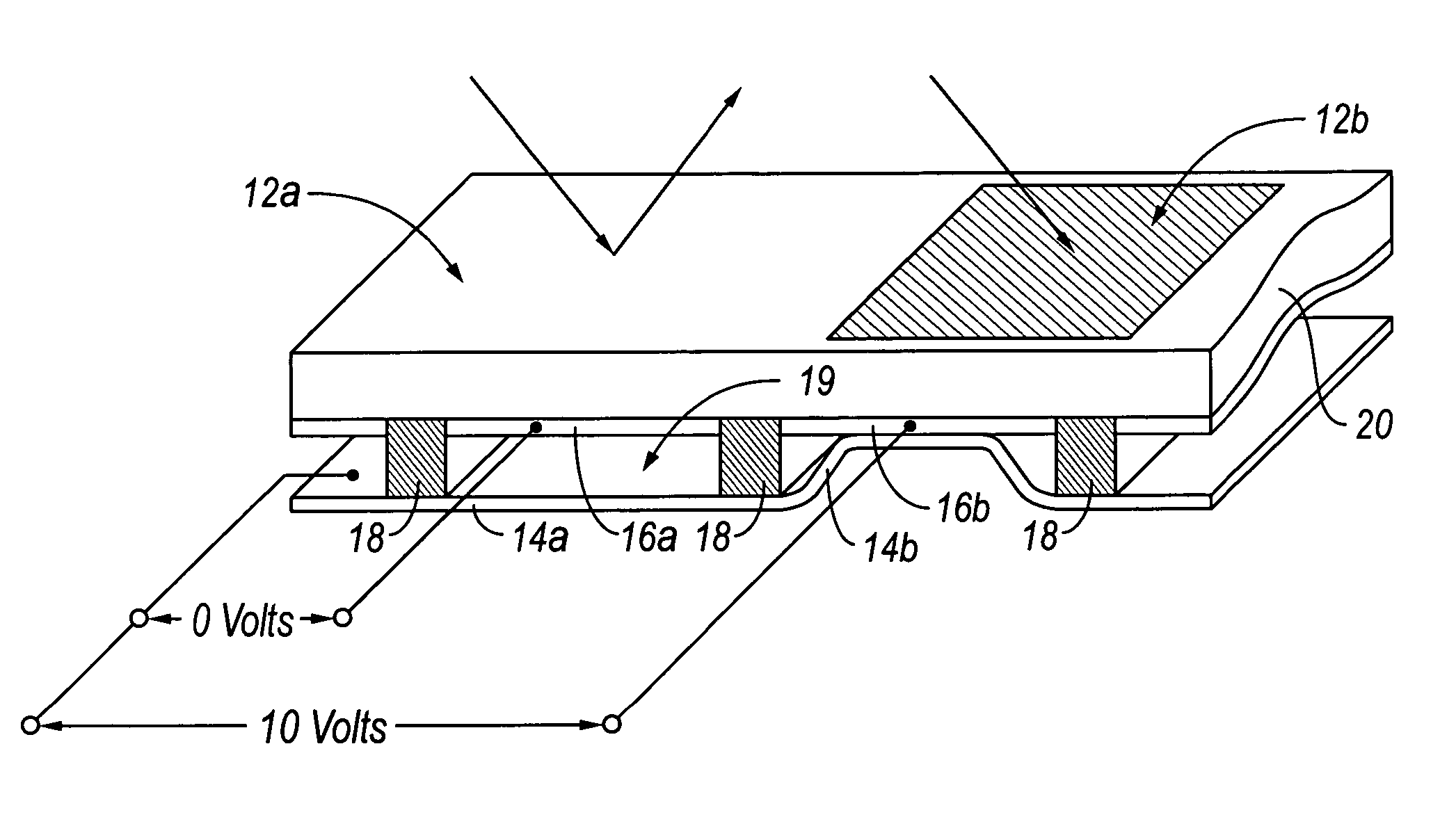
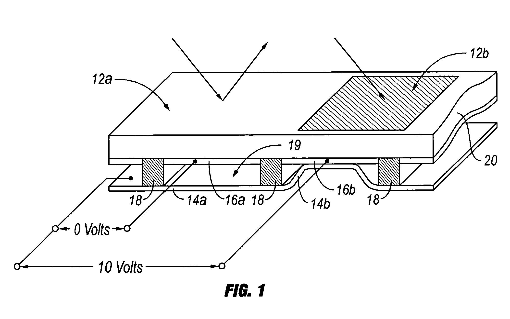
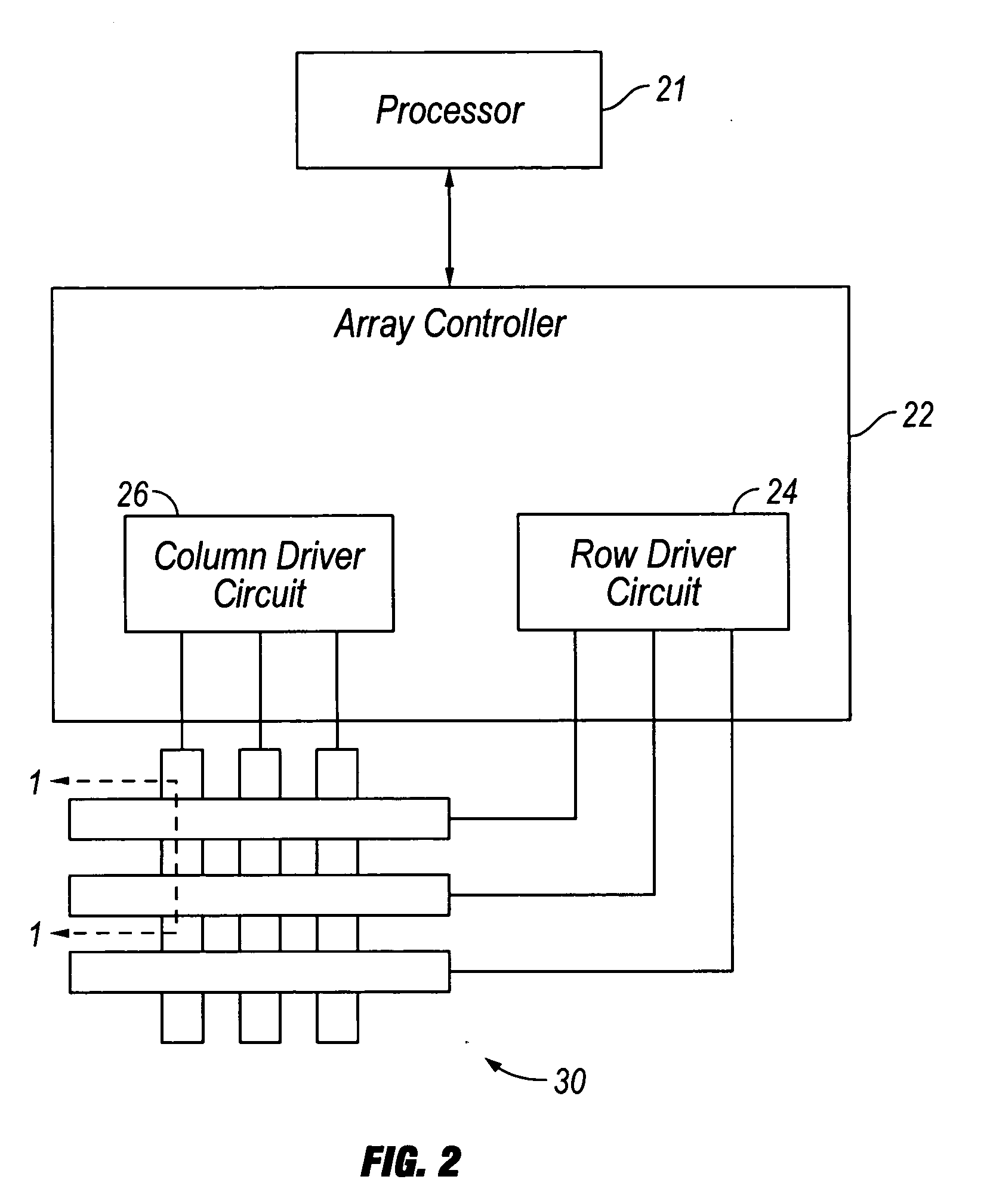
[0072] The following detailed description is directed to certain specific embodiments of the invention. However, the invention can be embodied in a multitude of different ways. In this description, reference is made to the drawings wherein like parts are designated with like numerals throughout. As will be apparent from the following description, the embodiments may be implemented in any device that is configured to display an image, whether in motion (e.g., video) or stationary (e.g., still image), and whether textual or pictorial. More particularly, it is contemplated that the embodiments may be implemented in or associated with a variety of electronic devices such as, but not limited to, mobile telephones, wireless devices, personal data assistants (PDAs), hand-held or portable computers, GPS receivers / navigators, cameras, MP3 players, camcorders, game consoles, wrist watches, clocks, calculators, television monitors, flat panel displays, computer monitors, auto displays (e.g., o...


PUM


Abstract

Process control monitors are disclosed that are produced using at least some of the same process steps used to manufacture a MEMS device. Analysis of the process control monitors can provide information regarding properties of the MEMS device and components or sub-components in the device. This information can be used to identify errors in processing or to optimize the MEMS device. In some embodiments, analysis of the process control monitors may utilize optical measurements.

Description

CROSS-REFERENCE TO RELATED APPLICATIONS [0001] This application is a divisional of U.S. application Ser. No. 11 / 198,888, filed Aug. 5, 2005, which claims priority to U.S. Provisional Application No. 60 / 613,537, filed on Sep. 27, 2004, both of which are incorporated herein by reference in their entirety. This application is also related to co-pending application Ser. No. ______, entitled “Process Control Monitors for Interferometric Modulators,” filed Nov. 17, 2005, attorney docket no. IRDM.152DV1; application Ser. No. ______, entitled “Process Control Monitors for Interferometric Modulators,” filed Nov. 17, 2005, attorney docket no. IRDM.152DV2; and application Ser. No. ______, entitled “Process Control Monitors for Interferometric Modulators,” filed Nov. 17, 2005, attorney docket no. IRDM.152DV3; all of which are incorporated herein by reference in their entirety.BACKGROUND OF THE INVENTION [0002] 1. Field of the Invention [0003] The field of the invention relates to microelectrome...

Claims


Application Information

Patent Timeline
Patent Type & Authority Applications(United States)
IPC IPC(8): G01B11/02B81C99/00
CPCB81B2201/042B81C99/004G02B26/001G01N21/9501G01N21/55G02B26/00
Inventor CUMMINGS, WILLIAMGALLY, BRIAN
Owner SNAPTRACK
Learn More