Collector plate for rechargeable battery, electrode assembly, and rechargeable battery comprising the same

Inactive Publication Date: 2006-03-30
SAMSUNG SDI CO LTD
View PDF5 Cites 16 Cited by
  • Summary
  • Abstract
  • Description
  • Claims
  • Application Information

AI Technical Summary

Problems solved by technology

If the rechargeable battery has only one lead terminal that couples the electrode group with an external terminal in the cap assembly, a voltage generated from each part of the electrode assembly cannot be collected easily.
This causes a potential difference between the region where the lead terminal is coupled to the electrode group and the other portions of the electrode group.
This potential difference deteriorates the portion where the lead terminal is welded to the electrode group as the rechargeable battery is repeatedly discharged and recharged.
This may cause the performance and lifespan of the rechargeable battery to diminish.
This problem is more serious for batteries that drive a motor, which repeatedly discharges and recharges in a short time.
However, in the above-mentioned conventional rechargeable battery, due to a structural limitation of the above-mentioned collector plate, the collector plate may easily deform or may easily break during the assembly of the rechargeable battery.
Further, since the collector plate cannot be grasped easily by ajig when the collector plate is welded, it is difficult to weld the collector plate at a precise position.

Method used


Image

  • Collector plate for rechargeable battery, electrode assembly, and rechargeable battery comprising the same
  • Collector plate for rechargeable battery, electrode assembly, and rechargeable battery comprising the same
  • Collector plate for rechargeable battery, electrode assembly, and rechargeable battery comprising the same

Examples


Embodiment Construction

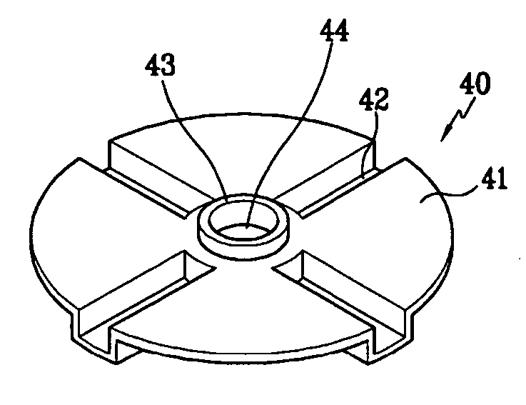
[0023] The rechargeable battery of the present invention comprises a collector plate that may be grasped easily by a jig when the collector plate is coupled with the electrode assembly by the protruding portion, which protrudes outward from the collector plate. As a result, the deformation of the collector plate during coupling with the electrode assembly may be prevented and performance of the rechargeable battery may improve These properties make the rechargeable battery of the present invention suitable for use as the power source for high power motor-driven devices such as electric vehicles, hybrid electric vehicles, wireless vacuum cleaners, motorbikes, and motor scooters.

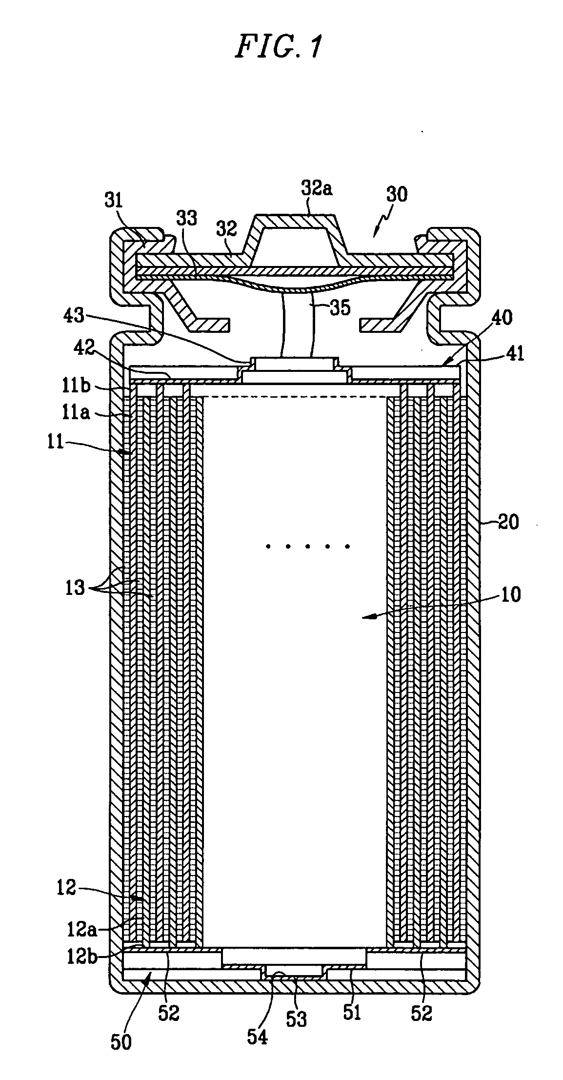
[0024]FIG. 1 is a cross-sectional view of a rechargeable battery according to an exemplary embodiment of the present invention.

[0025] As shown in FIG. 1, the rechargeable battery may include an electrode group 10 including a positive electrode 11 and a negative electrode 12 with a separator 13 interposed the...


PUM


Abstract

A rechargeable battery comprises an electrode group including a positive electrode, a negative electrode with a separator interposed therebetween, a case in which the electrode group is inserted, a cap assembly that is coupled with the case to seal the case, and collector plates that are coupled with the electrode group to transfer an electric current to external terminals. In addition, the collector plates comprise protruding portions that protrude outward from a surface of each of the collector plates.

Description

CROSS REFERENCE TO RELATED APPLICATION [0001] This application claims priority to and the benefit of Korean Patent Application No. 10-2004-0077053, filed in the Korean Intellectual Property Office on Sep. 24, 2004, the entire disclosure of which is incorporated herein by reference for all purposes as if fully set forth herein. BACKGROUND OF THE INVENTION [0002] 1. Field of the Invention [0003] The present invention relates to a rechargeable battery comprising collector plates with an improved structure. [0004] 2. Description of the Background [0005] Unlike a nonrechargeable battery, a rechargeable battery may be charged and discharged repeatedly. A low capacity battery comprising a single battery cell may be used as a power source for various portable electronic devices such as cellular phones, notebook computers, and camcorders. A high power battery in which numerous battery cells are connected to each other in a battery pack unit may be used as a power source for driving a motor o...

Claims


Application Information

Patent Timeline
IPC IPC(8): H01M2/26H01M4/02H01M4/13H01M10/04H01M10/05H01M10/058H01M10/0587H01M50/533H01M50/538
CPCH01M2/022Y02E60/122H01M10/0431H01M2/263Y02E60/10H01M50/107H01M50/538Y02P70/50H01M50/533H01M4/70H01M10/0422H01M2220/30H01M2220/20Y02T10/70
Inventor YOO, SEOK-YOONKIM, YONG-SAM
Owner SAMSUNG SDI CO LTD
Why Eureka
Try Eureka