Bone fixation device

a bone fixation device and bone technology, applied in the field of bone fixation devices, can solve problems such as limiting the rigidity of the whole device, and achieve the effect of simplifying the design and reducing the dimensions of the bone fixation elements

Inactive Publication Date: 2006-03-30
SYNTHES USA
View PDF2 Cites 163 Cited by
  • Summary
  • Abstract
  • Description
  • Claims
  • Application Information

AI Technical Summary

Benefits of technology

[0009] The advantages of the present invention make it possible to dispense with the complicated and time-consuming activity of adapting the rigid longitudinal support members to a patient's anatomy—without having to accept the disadvantages of using flexible longitudinal support members. In addition, once the bone fixation elements on the spinal column have successfully been connected, it is still possible to modify the position of the individual bone fixation elements relative to one another. The new positions of the concerned vertebral bodies relative to one another (spinal column correction) may be kept in place by blocking the flexible connecting members within the bone fixation elements. The elasticity of the flexible connecting members permits them to be inserted through an operative approach limiting soft-tissue injury to a minimum.
[0026] the position of the individual bone fixation elements relative to one another may be changed and fixed in a new position without having to remove the connecting members inserted therein.

Problems solved by technology

By blocking the flexible connecting members in the passages of two adjacent bone fixation elements, their displaceability within the passages is inhibited, which results in conveying rigidity to the whole device.

Method used


Image

  • Bone fixation device
  • Bone fixation device
  • Bone fixation device

Examples


Embodiment Construction

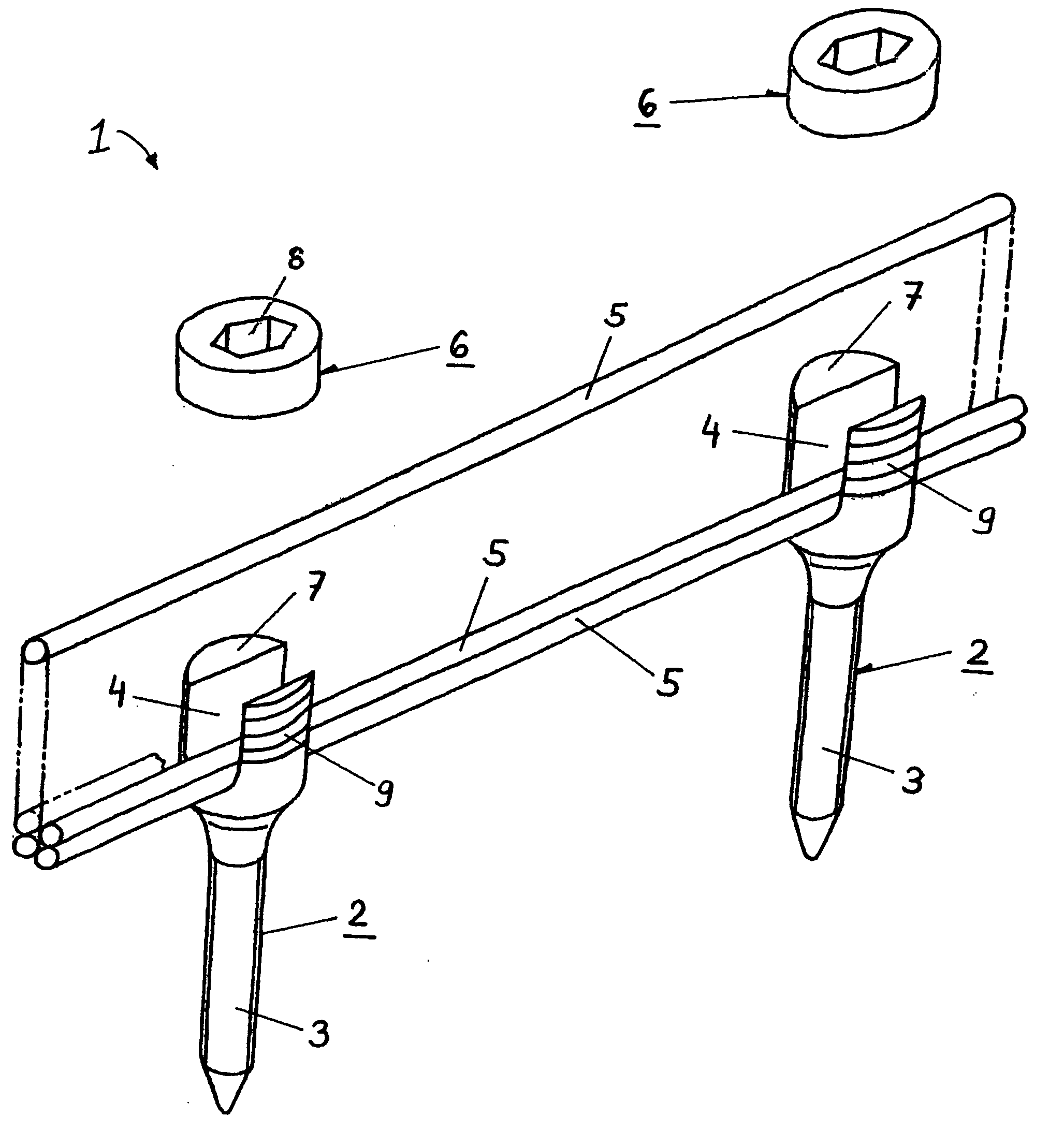
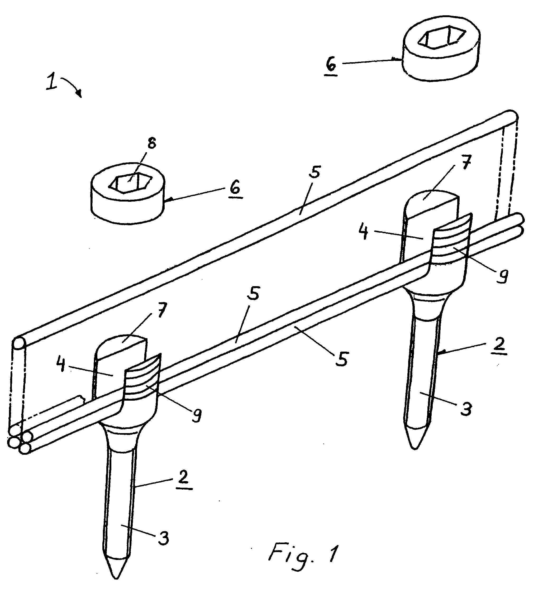
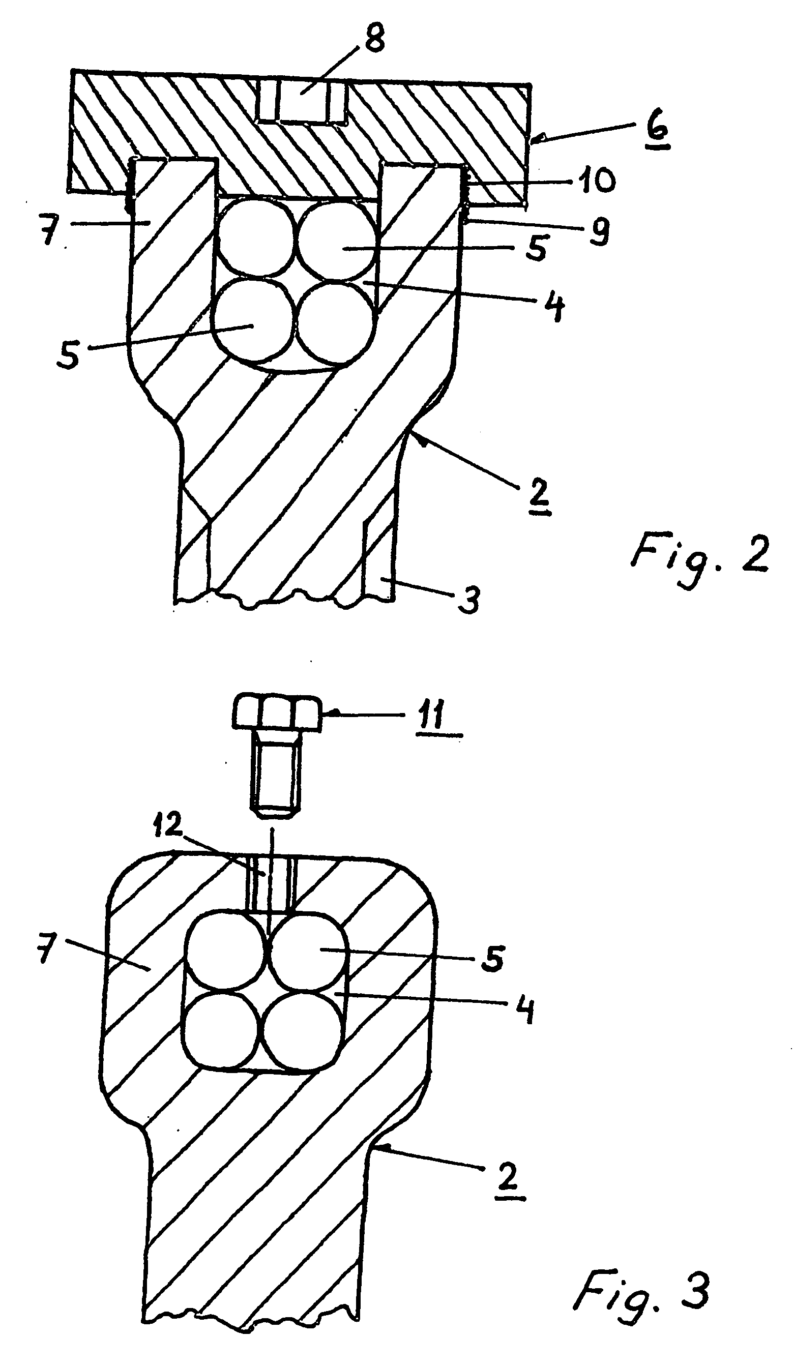
[0031]FIG. 1 shows a bone fixation device 1 that includes two bone fixation elements 2 (in the form of pedicle screws) and four longitudinal, flexible connecting members 5. Connecting members 5 are shaped in the form of thin, flexible rods that are connectable to bone fixation elements 2. Bone fixation elements 2 each have a portion 3 in the form of a threaded shank which may be anchored in the bone. Fixation elements 2 also have a head 7 having a U-shaped passage 4. Passages 4 of bone fixation elements 2 may be closed by means of a blocking element 6, which may be in the form of a hollow cap 6 having an internal screw thread 10 (see FIG. 2) and a hexagonal socket 8. The head 7 of each bone fixation element 2 has a corresponding external screw thread 9 to which the blocking element 6 may be screwed on in such a way that the longitudinal, flexible connecting members 5 inserted in passage 4 are fixed in their position both relative to one another and to the respective bone fixation el...


PUM


Abstract

A bone fixation device for use in, for example, spinal column surgery, includes at least two bone fixation elements that each have a passage and a portion to be anchored on or in the bone. The device also includes at least two longitudinal, flexible connecting members that can be inserted and fastened in the passages of two adjacent fixation elements. The device can flexibly adapt to a patient's anatomy and to desired surgical results during the implantation of the device, and can then be rendered entirely rigid by simply blocking the fixation elements relative to one another. In addition, use of the device in the surgical treatment of the spinal column is minimally invasive.

Description

CROSS REFERENCE TO RELATED APPLICATION [0001] This is a continuation of International Patent Application No. PCT / CH2003 / 00253, filed Apr. 15, 2003, the entire contents of which are incorporated herein by reference thereto.TECHNICAL FIELD OF THE INVENTION [0002] The invention relates to bone fixation devices. More particularly, the invention relates to bone fixation devices that have flexible connecting members clamped in bone fixation elements that result in a rigid structure. BACKGROUND OF THE INVENTION [0003] Most known spinal column stabilization systems use rigid connecting rods to connect the elements anchored in a spinal column. These rigid connections make it possible to fixedly set the desired spinal column adjustments made by a surgeon. The disadvantage of such rigid connections lies in their use during a surgical procedure. Only in exceptional cases will the surgeon succeed in attaching a plurality of anchoring elements to the spinal column such that they can be connected ...

Claims


Application Information

Patent Timeline
Patent Type & Authority Applications(United States)
IPC IPC(8): A61F2/30A61B17/00A61B17/70
CPCA61B17/7029A61B2017/00862A61B2017/00858A61B17/7032
Inventor FRIGG, ROBERTLANG, BRUNO
Owner SYNTHES USA
Why Eureka
Try Eureka