Measurement method using blurred images

a measurement method and blurred image technology, applied in image analysis, instruments, computing, etc., can solve the problems of low cost speed measurement method and high equipment used in the implementation of speed detectors, and achieve the effect of simplifying the speed measurement of deblurred image of detected objects, and reducing the cost of speed measurement equipmen

a measurement method and blurred image technology, applied in image analysis, instruments, computing, etc., can solve the problems of low cost speed measurement method and high equipment used in the implementation of speed detectors, and achieve the effect of simplifying the speed measurement of deblurred image of detected objects, and reducing the cost of speed measurement equipmen

US20060078164A1Inactive Publication Date: 2006-04-13NATIONAL CHUNG CHENG UNIV

Image

  • Measurement method using blurred images
  • Measurement method using blurred images
  • Measurement method using blurred images

Examples


Embodiment Construction

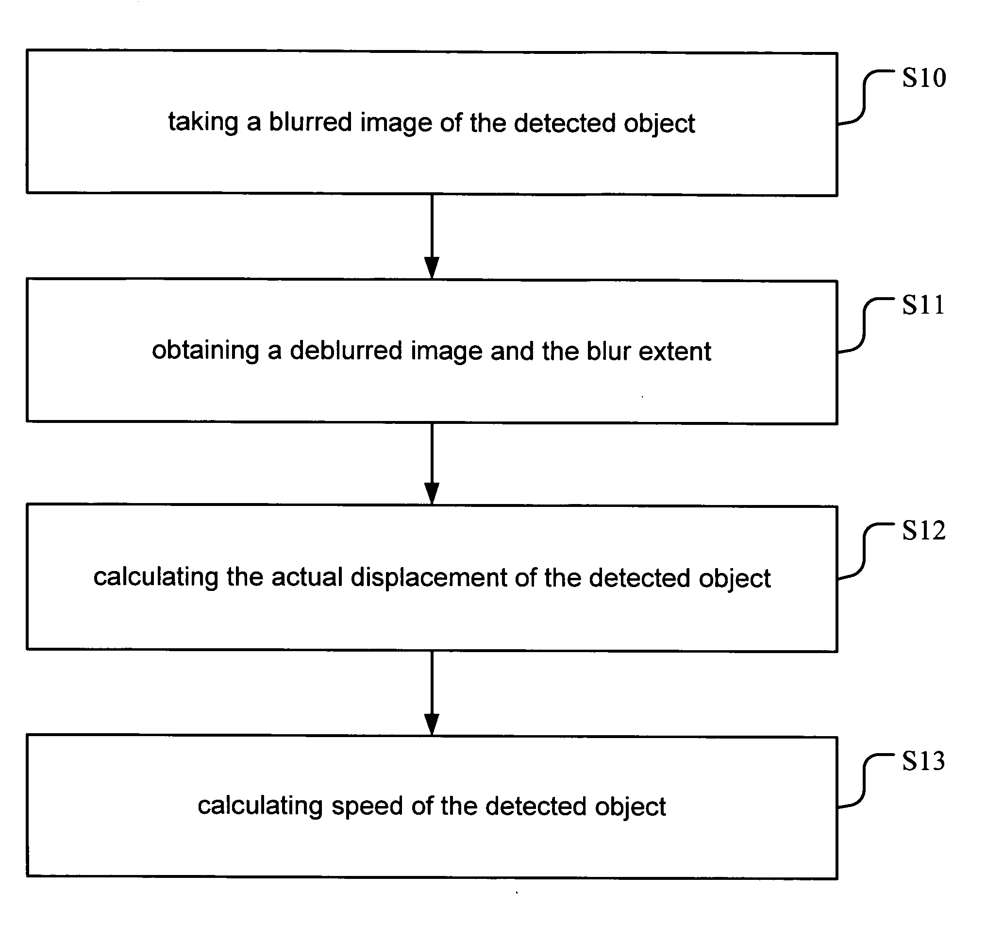
[0019] Most of the conventional methods for speed measurement are achieved by a laser detector that emits a pulse with a fixed frequency. The detector receives the reflected pulse from the detected object and converts it to an electric signal. A demodulator is then used to process the electric signal for the speed calculation of the detected object. This type of methods uses active devices, which are usually more expensive compared to a passive imaging system. Thus, a speed measurement method using blurred images in accordance with the present invention is provided. By using the blurred image of the detected object and the capturing parameters of the image-capturing device, the actual displacement of the detected object is estimated. The speed of the moving object is then calculated by using the actual displacement and the image capturing parameters.

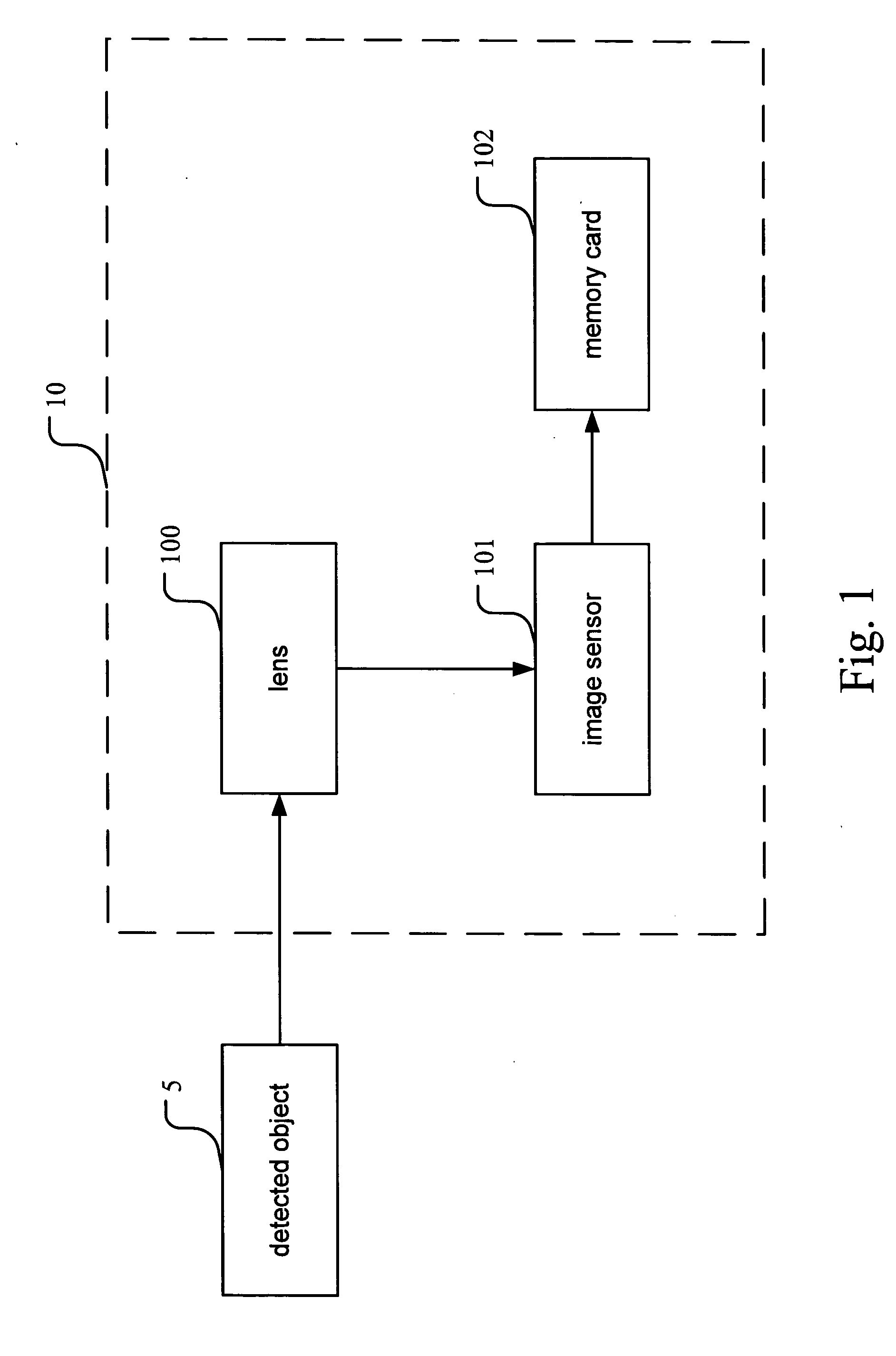
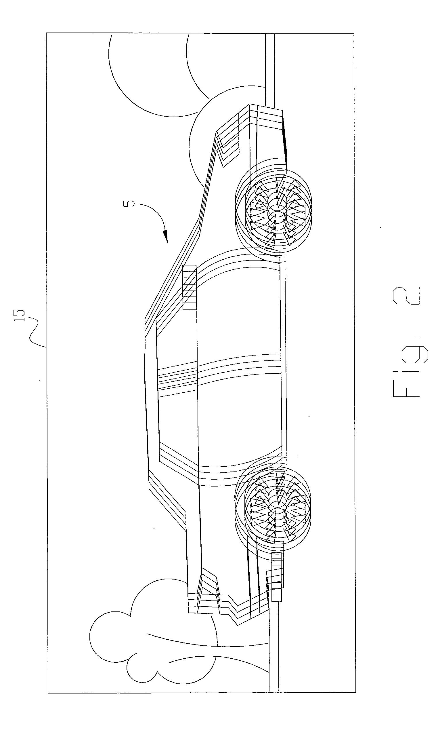
[0020] Refer to FIG. 1&FIG. 2; the present invention includes an image-capturing device 10 for taking a blurred image 15 of a detected...


PUM


Abstract

A speed measurement method using blurred images is for calculating the speed of moving objects being detected. By an image-capturing device, a blurred image of the detected object is obtained. The blurred image is used to create a deblurred image and obtain a blur extent. The speed of the detected object is then calculated by using the blur extent and the capturing parameters of the image-capturing device. In accordance with the above method, the cost of speed detectors is reduced.

Description

BACKGROUND OF THE INVENTION [0001] The present invention is related to a speed measurement method; especially to a speed measurement method using blurred images of objects for speed calculation of moving objects so that the cost of the speed detectors can be reduced. [0002] In recent years, because of the advance on the development of various aircrafts, baseball exercise, and electrical devices, people are getting more interested in knowing the speed of flying objects, the pitching speed of sports players, and the speeding of vehicles detected by the law enforcement agencies. Due to the increasing demands of high quality products for speed detection, the development of speed measurement methods varies from traditional single-point measurement to digital image techniques nowadays. Thus, developing a novel, efficient, and low cost speed measurement method is an important issue for both consumer products and the systems used for police staffs. [0003] Currently, most of speed measuremen...

Claims


Application Information

Patent Timeline
13 Apr 2006
Publication
US20060078164A1
IPC
G06K9/00; G01P3/38; G01S11/12; G06T7/20
CPC
G01P3/38; G01S11/12; G06T7/20
Inventors
LIN, HUEI-YUNG