Apparatus for storing material

a technology for storing apparatus and materials, applied in the direction of transportation and packaging, transportation items, loading/unloading vehicle arrangment, etc., can solve the problems of reducing affecting the overall storage volume of a particular storage device, and a single shape of a hopper may not be suitable for multiple different types of materials, etc., to achieve the effect of raising and lowering

Inactive Publication Date: 2006-04-13
HAGEMANN MR RONALD T
View PDF11 Cites 35 Cited by
  • Summary
  • Abstract
  • Description
  • Claims
  • Application Information

AI Technical Summary

Benefits of technology

[0006] One aspect of the present invention is directed toward an apparatus for storing material which includes a movable floor that can be raised and lowered by means of an inflatable bag to gravitationally discharge materials contained in a liner through a discharge port. This storage apparatus includes a containment vessel having a top and a bottom spaced below the top, and an outer sidewall extending generally around a periphery of the top and bottom and vertically between the top and the bottom. A liner in the storage apparatus contains material in the vessel. The liner is at least partially carried by the movable floor and provides a discharge port. The movable floor is arranged along the bottom of the containment vessel and includes a distal end spaced laterally from the discharge port and a proximate end arranged between the distal end and the discharge port. An inflatable bag is arranged at the bottom and under the movable floor approximate the distal end thereof. The inflatable bag has an inflated position raising the distal end of the movable floor f

Problems solved by technology

Thus, one shape of a hopper may not be suitable for multiple different types of materials.
Additionally, by sloping the sidewalls away from a bottom discharge port, the area used to create the slope occupies potential storage volume and thereby decreases the overall storage volume of a particular storage device.
Additionally, these types of storage devices are not versatile or modular and can typically only be used for one type of an application, such as holding and discharging dry flowable materials, and cannot be r

Method used


Image

  • Apparatus for storing material
  • Apparatus for storing material
  • Apparatus for storing material

Examples


Embodiment Construction

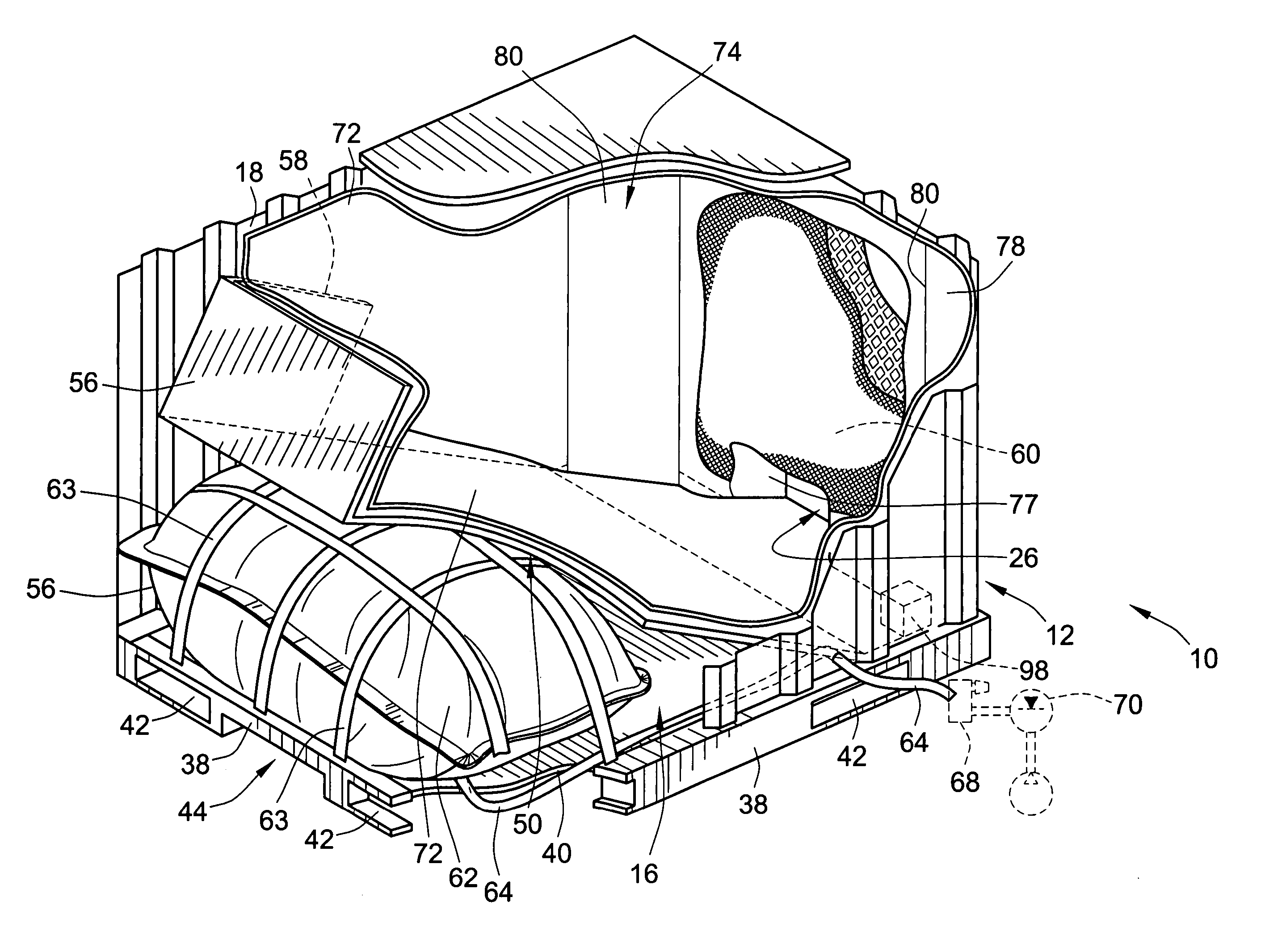
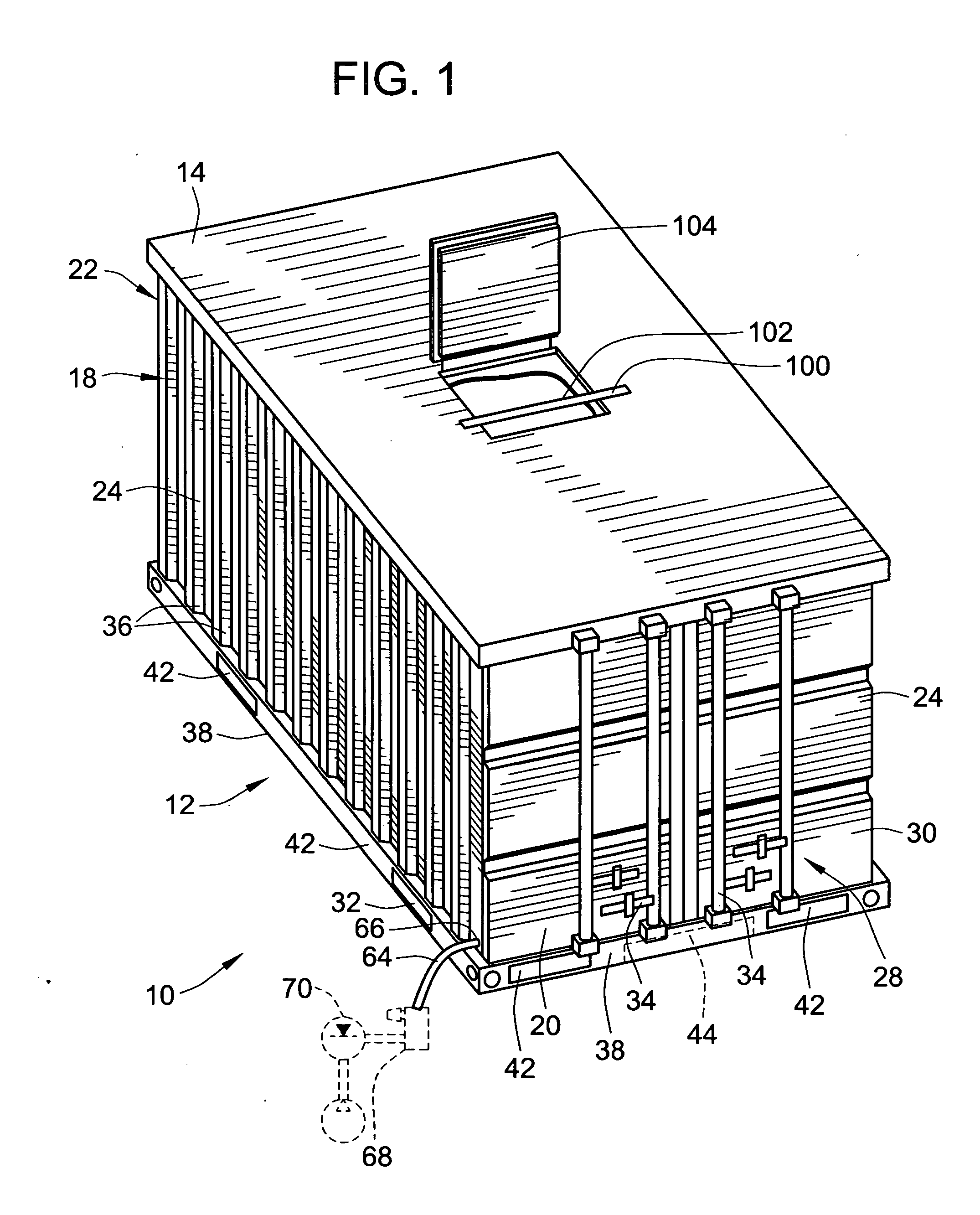
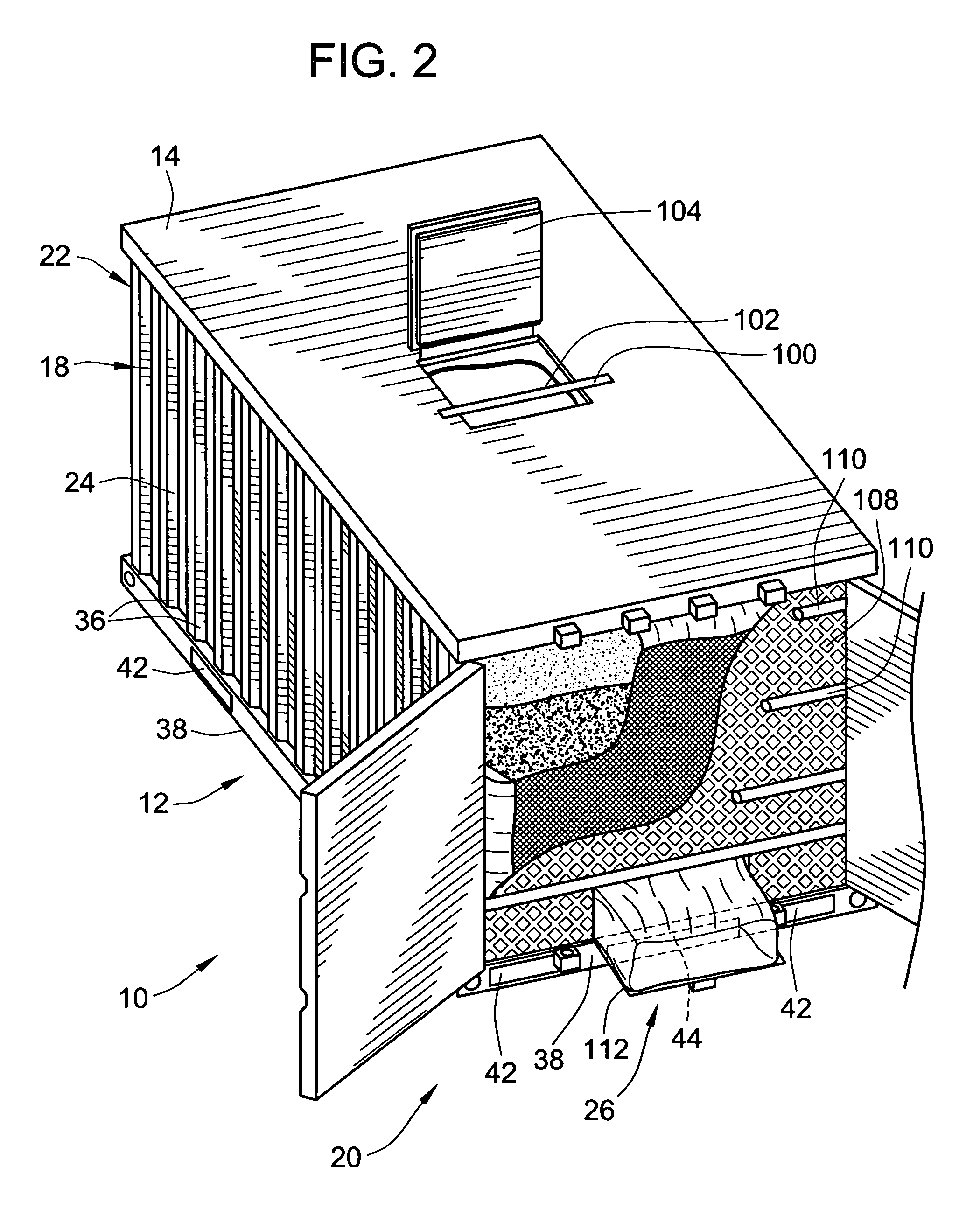
[0018] Referring to the figures, an embodiment of the present invention is depicted as a storage apparatus, which may be used to store a wide range of different materials (including liquids, generally dry flowable fluid materials such as grains, granular material, salt, etc.) and also for storing objects. As shown in the figures, a storage apparatus 10 includes a containment vessel 12 which provides the structural support and integrity of the storage apparatus 10. The containment vessel 12 is preferably a generally rectangular boxlike structure and may include a total of six different sides. As oriented according to the typical orientation, the containment vessel generally includes a top (which may be open, but is preferably enclosed and fully covered to include a top panel or ceiling), a bottom floor 16 spaced vertically below the top 14 and a sidewall 18 that extends perpendicularly between the top and the bottom floor and around the perimeter of the containment vessel 12. The sid...


PUM


Abstract

A new storage apparatus is provided which includes a rectangular box-like containment vessel in which a false movable floor is provided over the bottom floor. A dunnage bag or other actuator is provided to selectively raise and lower the false floor to facilitate self-evaluation and discharge of dry flowable material through a discharge port. The false floor structure may be removed to provide for versatility and different storage options. For example, the containment vessel can be left empty to provide for storage of other objects through openable doors or a pillow tank may be installed within the containment vessel to provide for liquid holding capabilities.

Description

FIELD OF THE INVENTION [0001] The present invention generally relates to containers and storage devices, and more particularly relates to apparatus which can contain and dispense generally dry material and / or may be modular for providing multiple different storage options. BACKGROUND OF THE INVENTION [0002] There are a wide variety of storage vessels that are commonly used in the storage and transportation industries. As applied to flowable materials (e.g. grain, rock salt, and the like) often storage vessels will be in the form of a hopper with slanted sidewalls which converge toward a discharge port. The discharge port will be associated with a closure device such as a gate which may be opened and closed to selectively retain or discharge material from the hopper. While such structures are widely used, there are several deficiencies with this type of a storage device, which will become more apparent once the present invention is understood. First, the slanted sidewalls must be fix...

Claims


Application Information

Patent Timeline
IPC IPC(8): B60P1/04
CPCB60P3/426B65D88/60B65D88/741B65D90/046B65D90/047B65D90/10B65D2590/046
Inventor HAGEMANN, RONALD T.
Owner HAGEMANN MR RONALD T
Why Eureka
Try Eureka