Flying insect trap

a technology insect traps, which is applied in the field of flying insect traps, can solve problems such as unpleasant appearance, and achieve the effect of easy removal

Inactive Publication Date: 2006-04-20
KILLGERM GROUP
View PDF13 Cites 29 Cited by
  • Summary
  • Abstract
  • Description
  • Claims
  • Application Information

AI Technical Summary

Benefits of technology

[0007] In one embodiment, a minimal insignificant or minor amount of light may also protrude onto a small portion of the wall adjacent to the attachment position of the trap on the wall. The attachment of the front cover to the rear cover can define a top opening and a bottom opening for entry by insects. Light is permitted to escape through either opening and insects enter the area define between the front and rear covers also through either opening where they are captured by a provided adhesive member, such as the sticky board. The light the escapes through the top and bottom opening is at least substantially captured by corresponding curved top and bottom ends of the rear cover. Elongated side openings can also be defined between the front cover and the rear cover, when the front cover is properly attached to the rear cover, to permit light to escape and be captured by the rounded side ends of the rear cover. Thus insects, such as flies attracted to the light, will enter either through bottom or top opening or possibly one of the side openings and ultimately be caught or captured by the exposed adhesive on the rear surface of the front cover. To replace the adhesive member and / or to change the light bulb, the front member is easily removed to permit easy access to the adhesive member and light bulb.

Problems solved by technology

These conventional traps are typically not pleasant in appearance and thus, distract from the overall ornamental decorative aspects of a room in which they are located.

Method used


Image

  • Flying insect trap
  • Flying insect trap
  • Flying insect trap

Examples


Embodiment Construction

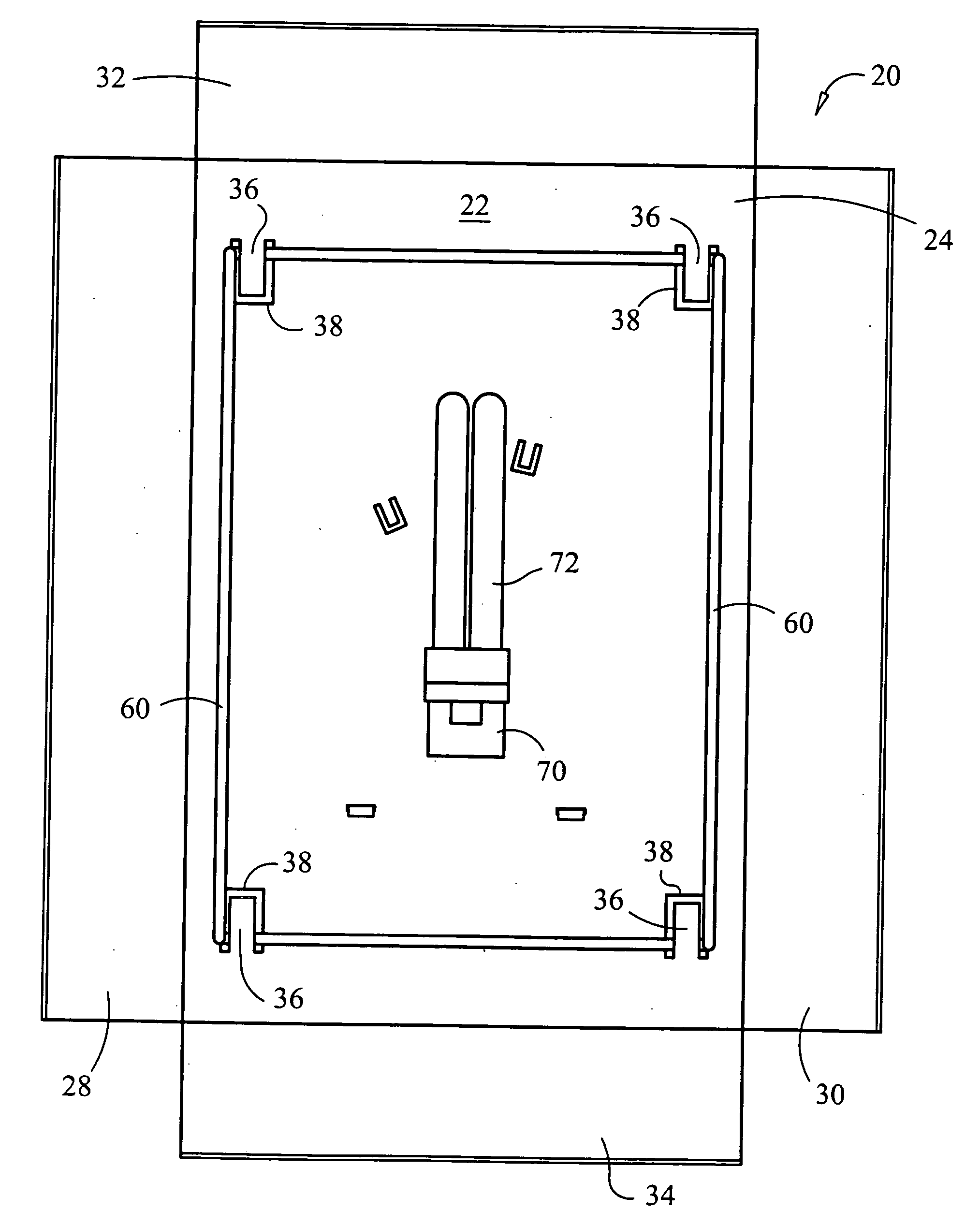
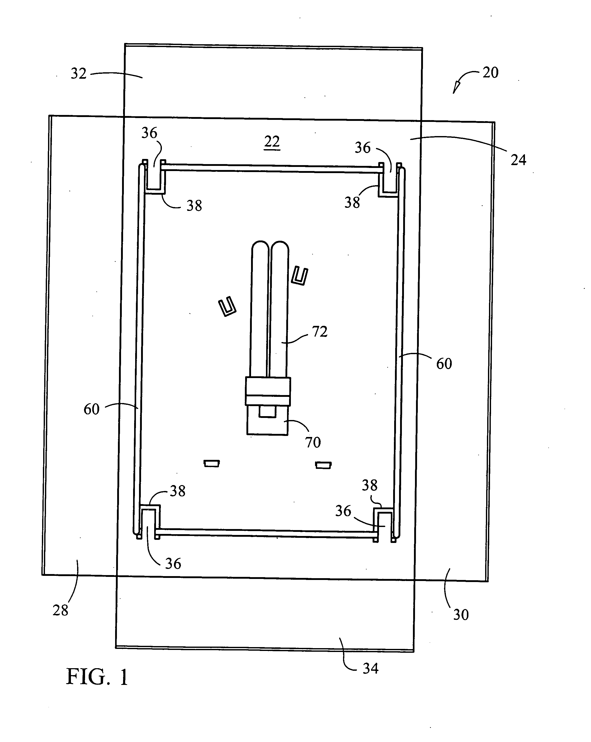
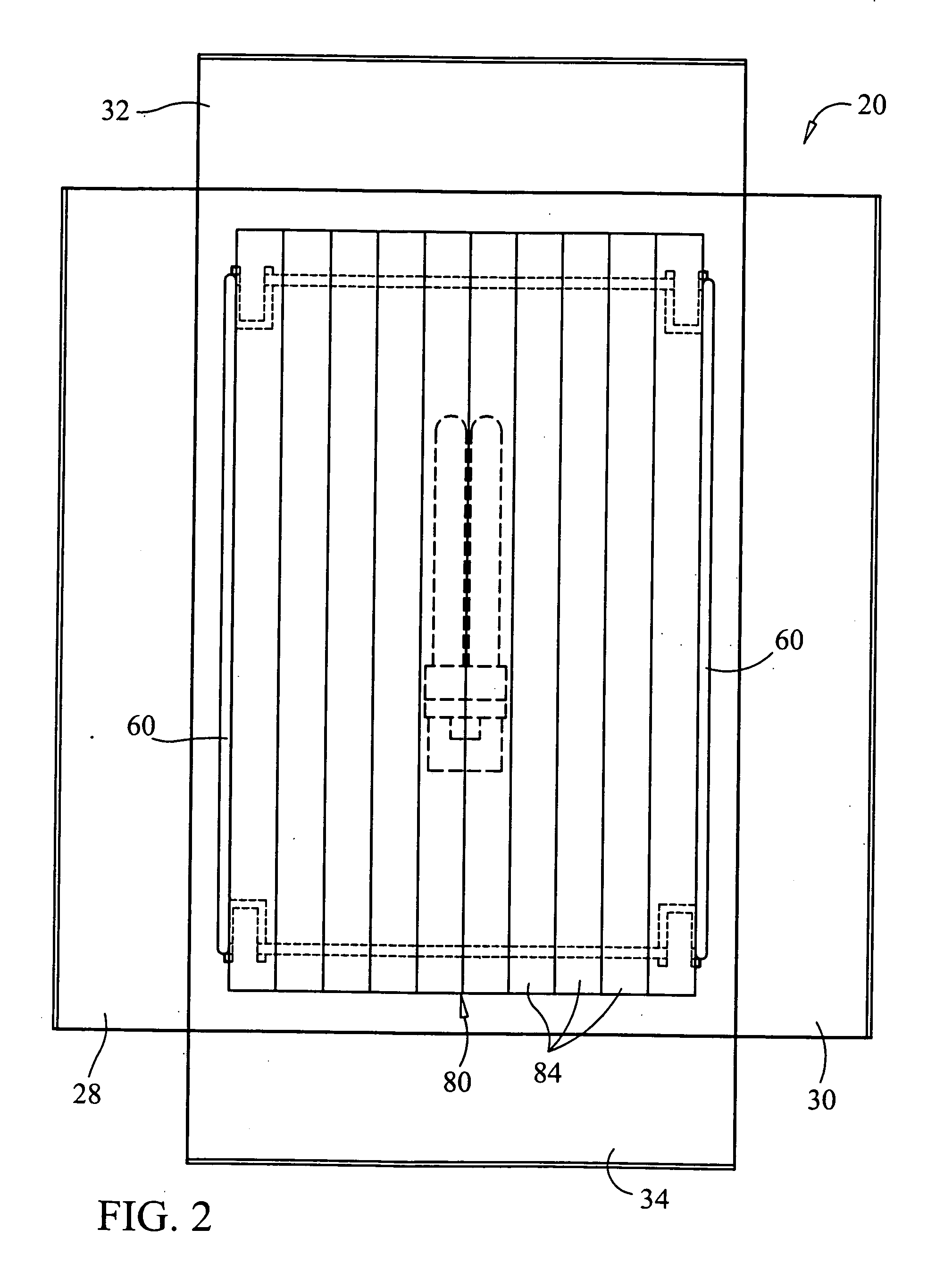
[0019] As seen in the drawings, an insect trap is provided for primarily attracting and capturing flying insects or bugs such as, but not limited to, flies. The trap can also be used to capture non-flying insects or buts, such as those that may climb up a wall of a room that the trap is mounted to. The insect trap is generally designated as reference numeral 20. Trap 20 can include a rear cover 22 which is connected to a separate and removable front cover 80. A light ballast or socket 70 can be attached to a front surface 24 of rear cover 22, and a mounting mechanism 56 can be attached to or otherwise associated with a back surface 26 of rear cover 22. Mounting mechanism 56 can also serve as a housing for the conventional wires or electronics (not shown) typically associated with light ballast / socket 70. An electrical cord 63, having a plug portion 65 can extend out of mounting mechanism 56.

[0020] One or more holes 58 and / or one or more holes 60 can be provided for mounting trap 20...


PUM


Abstract

An insect trap having a rear cover attached to a wall which is connected to a separate and removable front cover. The front cover can be primarily round in shape with a plurality of slats and a shiny exterior appearance. An adhesive member, such as a sticky board, can be attached to the rear surface of the front cover. A light bulb is disposed within a ballast/socket member attached to the front of the rear cover. Once plugged in, light from the bulb is primarily and substantially retained within the trap by its capture in view of the rounded ends of the rear cover. The light illuminates the trap itself to attract insects to the area between the rear and front covers where the adhesive member is positioned.

Description

[0001] This application claims priority to and the benefit of U.S. Application Ser. No. 60 / 619,440, filed Oct. 15, 2004 which is incorporated by reference in its entirety herein.FIELD OF THE INVENTION [0002] The present invention relates generally to pest control devices and more particularly to a flying insect trap. BACKGROUND OF THE INVENTION [0003] Current indoor bug lights typical reflect light onto the wall and ceiling of a room as a way of attracting flying insects to the trap. These conventional traps are typically not pleasant in appearance and thus, distract from the overall ornamental decorative aspects of a room in which they are located. Given the physical appearance of the traps, and that their shining lights also calls to their attention, use for the traps is most likely to be found in a commercial establishment. The present invention is intended to overcome the problems of past insect traps which use light to attract insects for capture by the trap. SUMMARY OF THE INV...

Claims


Application Information

Patent Timeline
Patent Type & Authority Applications(United States)
IPC IPC(8): A01M1/04A01M1/14
CPCA01M1/145A01M2200/012
Inventor GREENING, JOHN LLEWELLYN
Owner KILLGERM GROUP
Why Eureka
Try Eureka